


Nothing to see here.

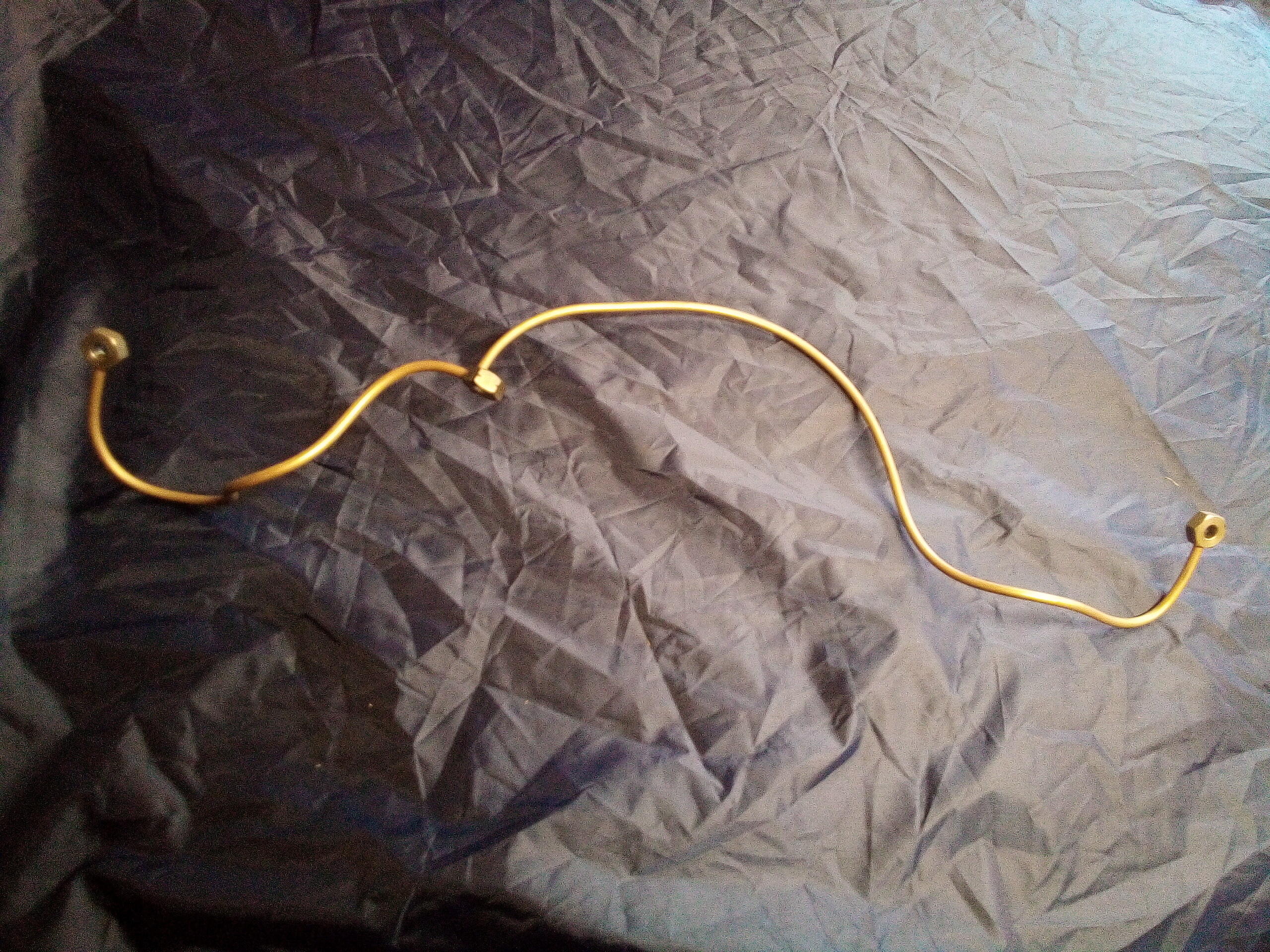
Being an air/oil cooled engine the pipes that feed oil to the 2CV’s cylinder heads are a key part of the system. They take oil fresh from the cooler and distribute it to the cylinder heads where it passes round the exhaust valve sleeve to cool it before entering the rocker covers to keep that area well lubricated, then returning down the push rod tubes to the sump.
The factory fitted steel pipes which, as they carry hot oil and are right at the front of the engine immediately behind the cooling fan, are somewhat susceptible to rust. When carrying out previous work I had noticed that there was a lot of surface rust on them but there’s no way of knowing how structurally compromised they were – and the consequences of a failure would be spraying high pressure oil onto the hot cylinder barrels, a situation that would be classed as far from ideal. A preemptive replacement with new, corrosion resistant, pipes was thus in order.
Whilst replacing them “only” involves three bolts, those bolts are located behind the tinware, which in turn is secured through the front engine mounts. And it’s behind the headlight mounting frame for good measure.

Removing all that lot falls into the category of “not technically difficult but laborious and time consuming”. However, once it’s done, access to the feed pipes is very good.

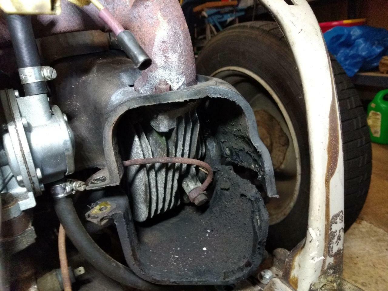
Removing the three banjo bolts (taking care to track which one came from which location as the one on the block is different to the ones on the heads) allows the pipes to lift off cleanly. Some new copper crush washers that came with the pipes were fitted, these are one – folded – spectacle type piece which are much easier to fit than individual washers that were used on the original.
The banjo bolts were refitted and tightened to a torque of 11 Nm (8 ft lbs) – being steel bolts going into lumps of aluminum this torque is both low and very important to observe. (It’s also less than the lie of 13 Nm printed in the
book of lies Haynes manual.)

With the tinware off it was a good time to do another job whilst the access was good: replace the manifold seals. (TL;DR: unbolt the manifold, lift it up, replace the seals, then bolt back on.)
In order to do that the manifold had to come off which made it a good time to do another job: re-torque the heads. (TL;DR: slacken off the head bolts then re-torque per the manual.)
In order to do that the rocker covers had to come off which made it a good time to do another job: replace the rocker retaining bolts.
After doing that it was a good time to do another job: adjust the valve rocker clearances.
Thanks to TomB engineering and the Kung-Fu Panda for their invaluable help with this job.

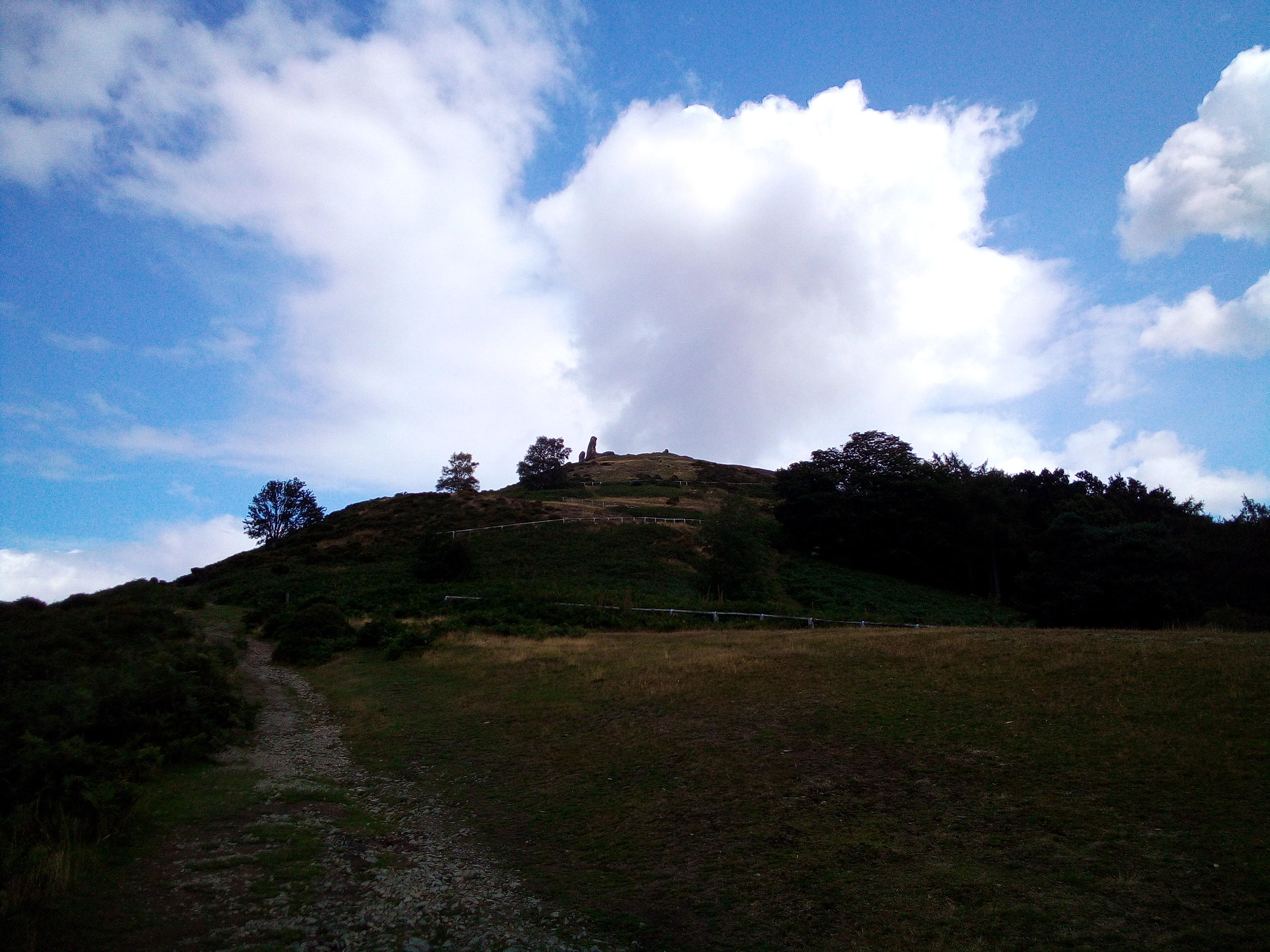
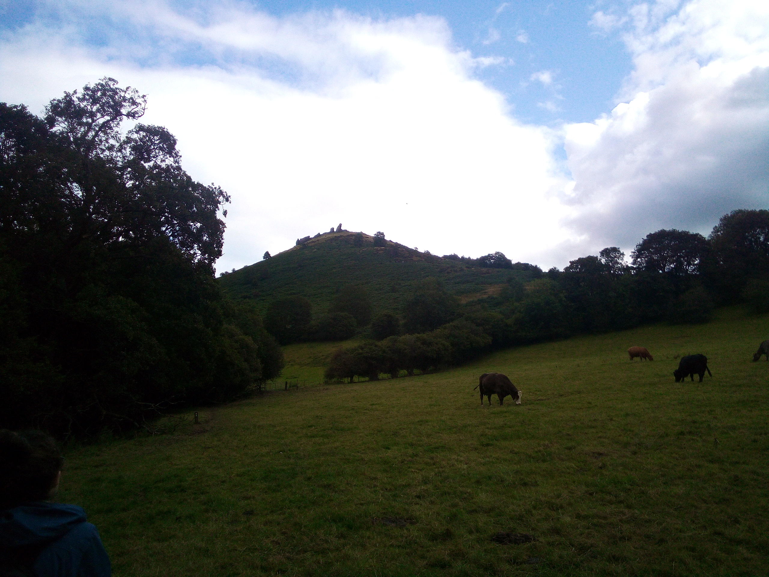
Took a walk up, over, down and round the castle fortress of Bran.
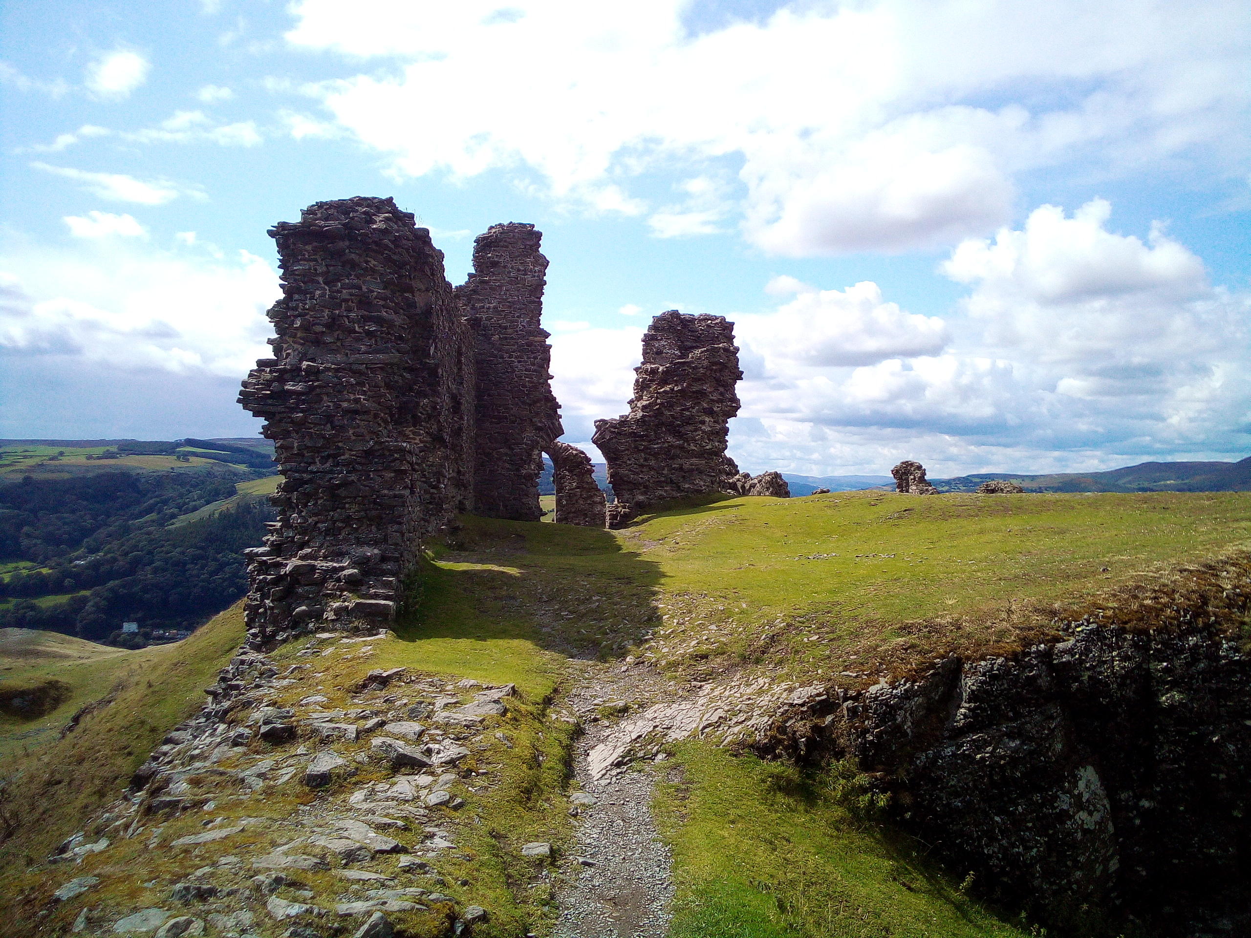

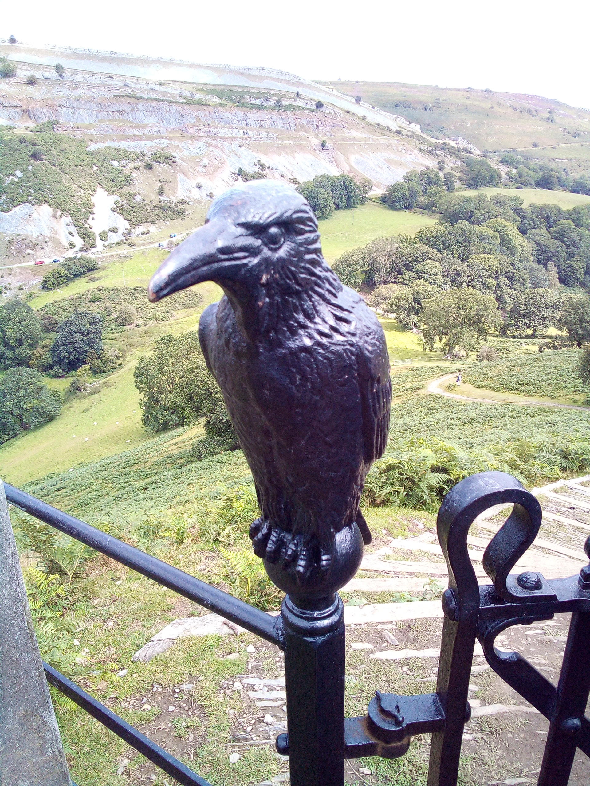
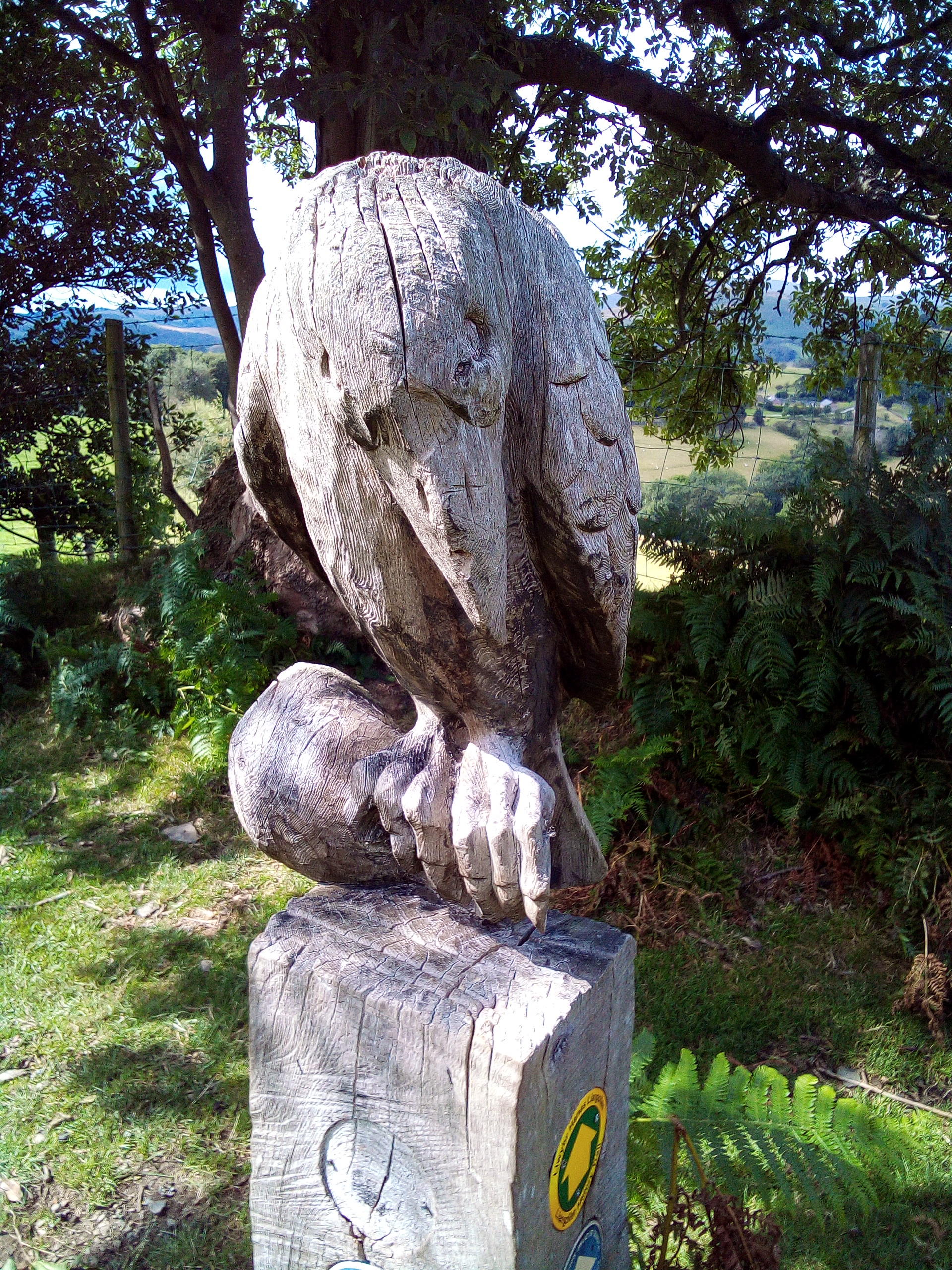
As Brân is Welsh for raven there were some raven sculptures on the path.
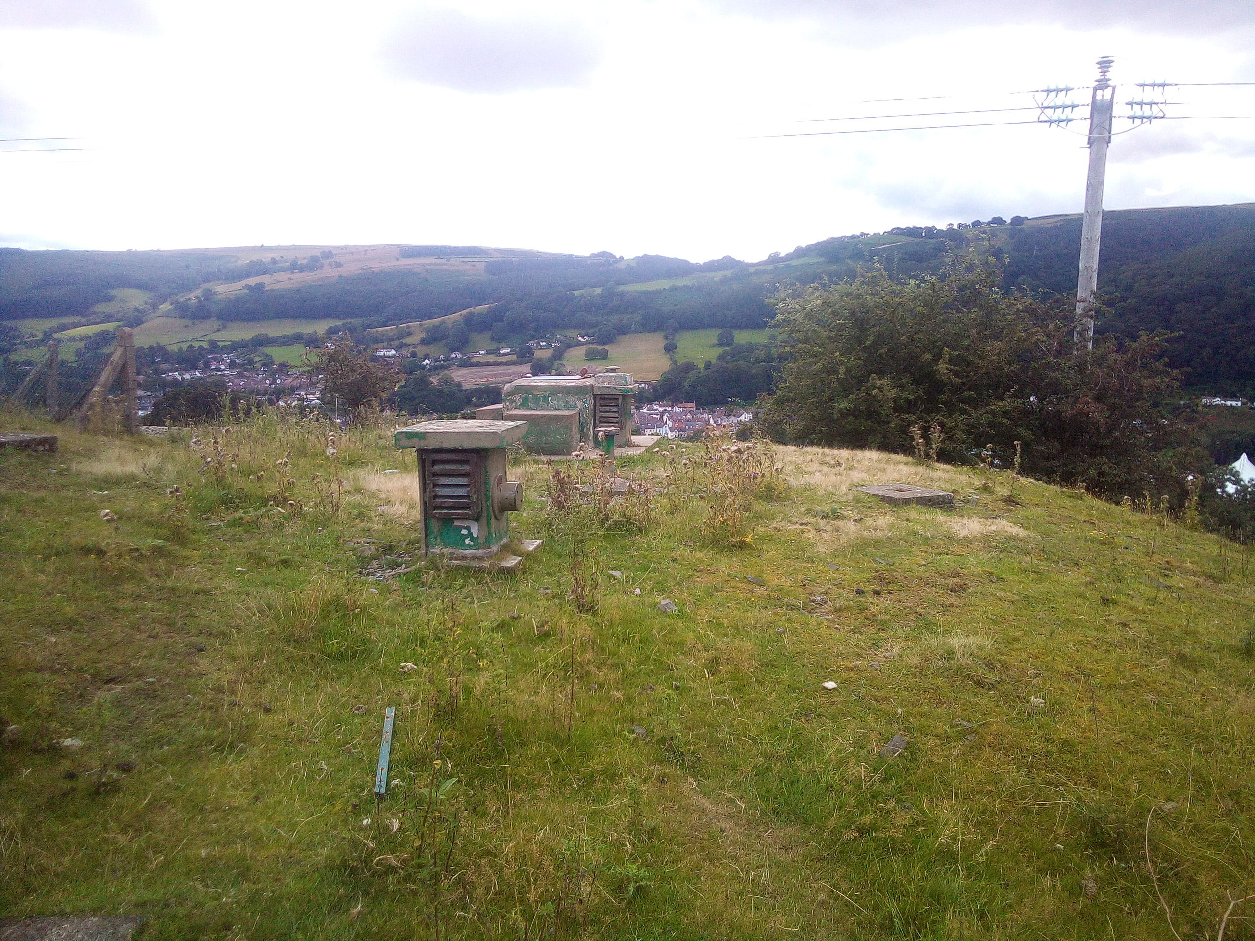
On the way down towards Llangollen I spotted an ROC post in a field.

The 2CV’s boot is spacious but the floor isn’t very flat which makes it a bit impractical to use.
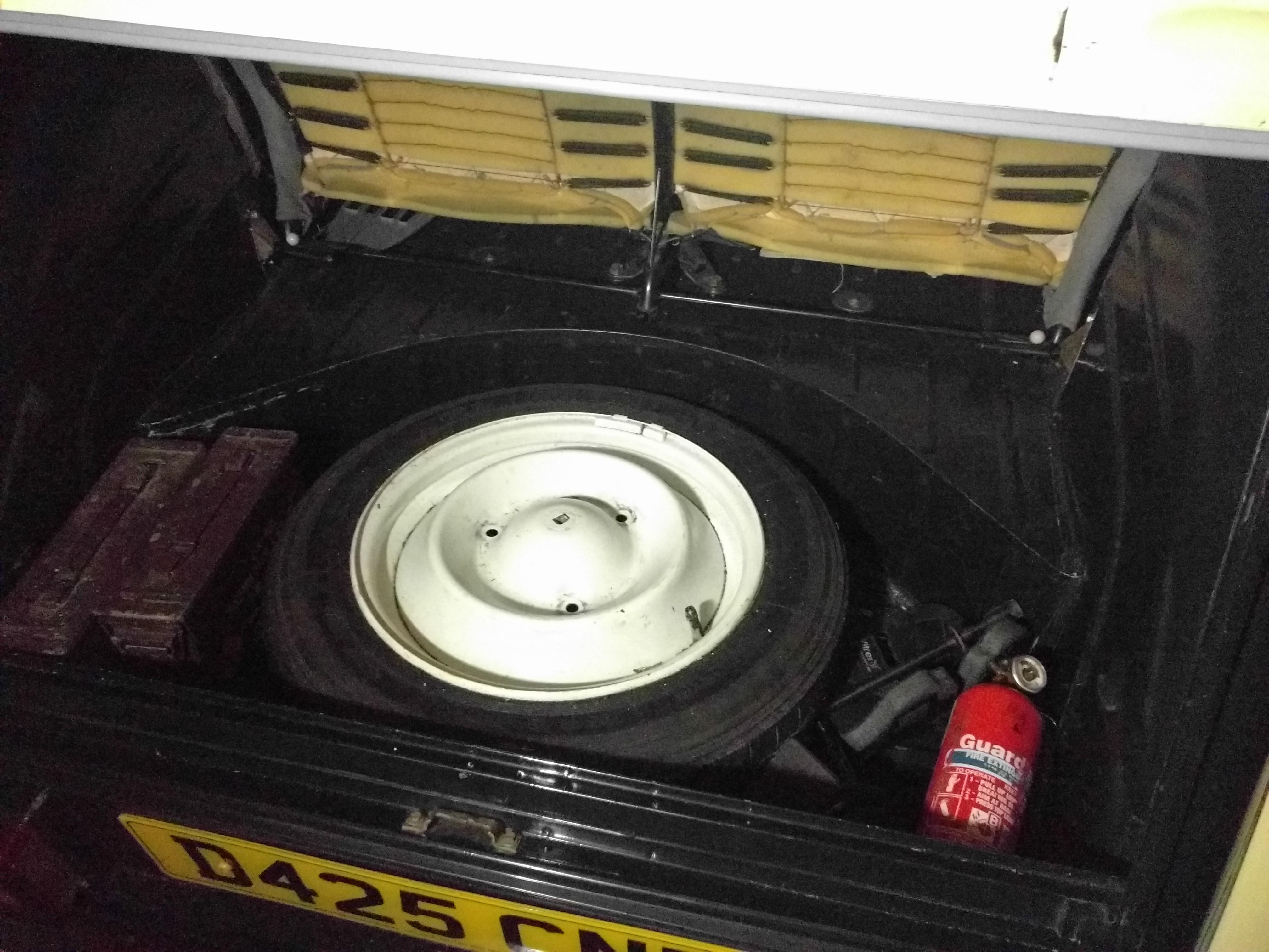
To improve this I’ve added a boot floor. This is a piece of 680mm x 940mm plywood with a notch cut in the back edge to fit round the central support for the back seats and a couple of notches in the front corners to allow it to slide forward through the boot opening thus allowing the back edge to clear the back seat and lift out. There’s also a small block of wood glued and screwed into the middle of the front edge to stop it sliding forward.

With the basic shape fitted I covered it with some bluegrey automotive carpet which provides a nice usable boot floor and the tools and spare wheel live happily under it and out of the way.


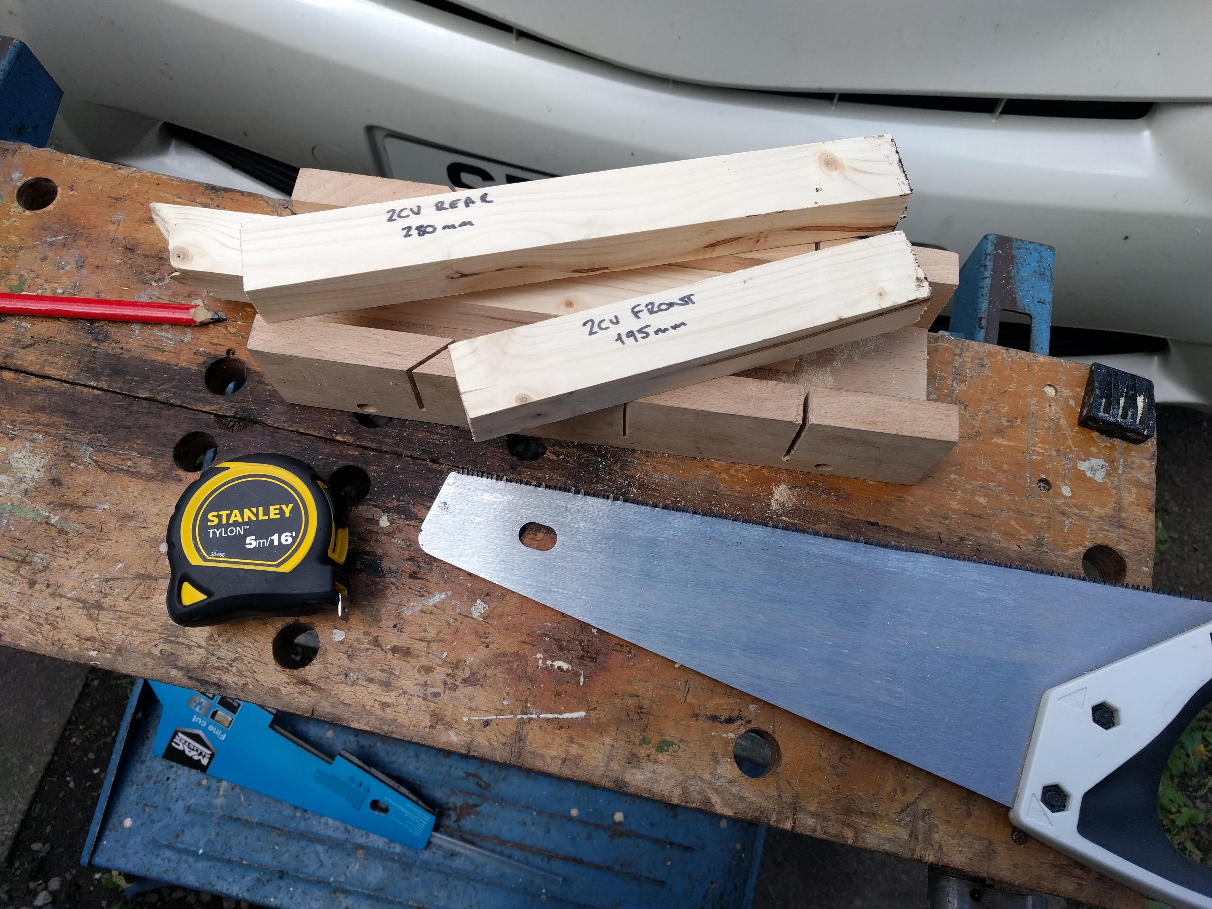
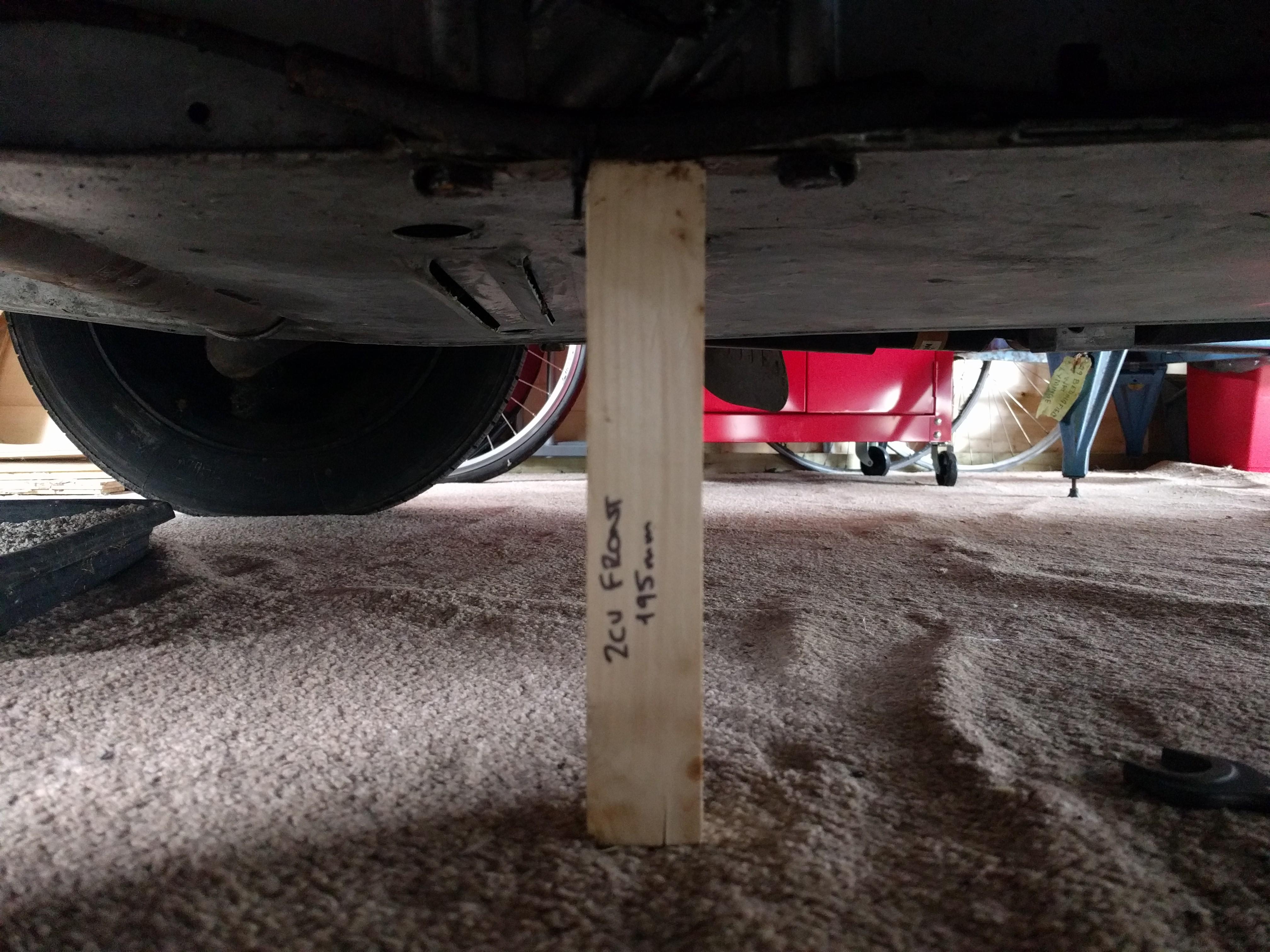
To set the ride height on a 2CV you really need two things: a flat and level surface and a 9-22mm tie rod adapter. When changing the chassis we had the former but not the latter and when I subsequently acquired the latter I didn’t have the former. Now I have both…
To make measurement easier I cut two bits of wood to the lengths of the required chassis height as measured between the axle bolts, 195mm at the front and 280mm at the rear (±2.5mm).
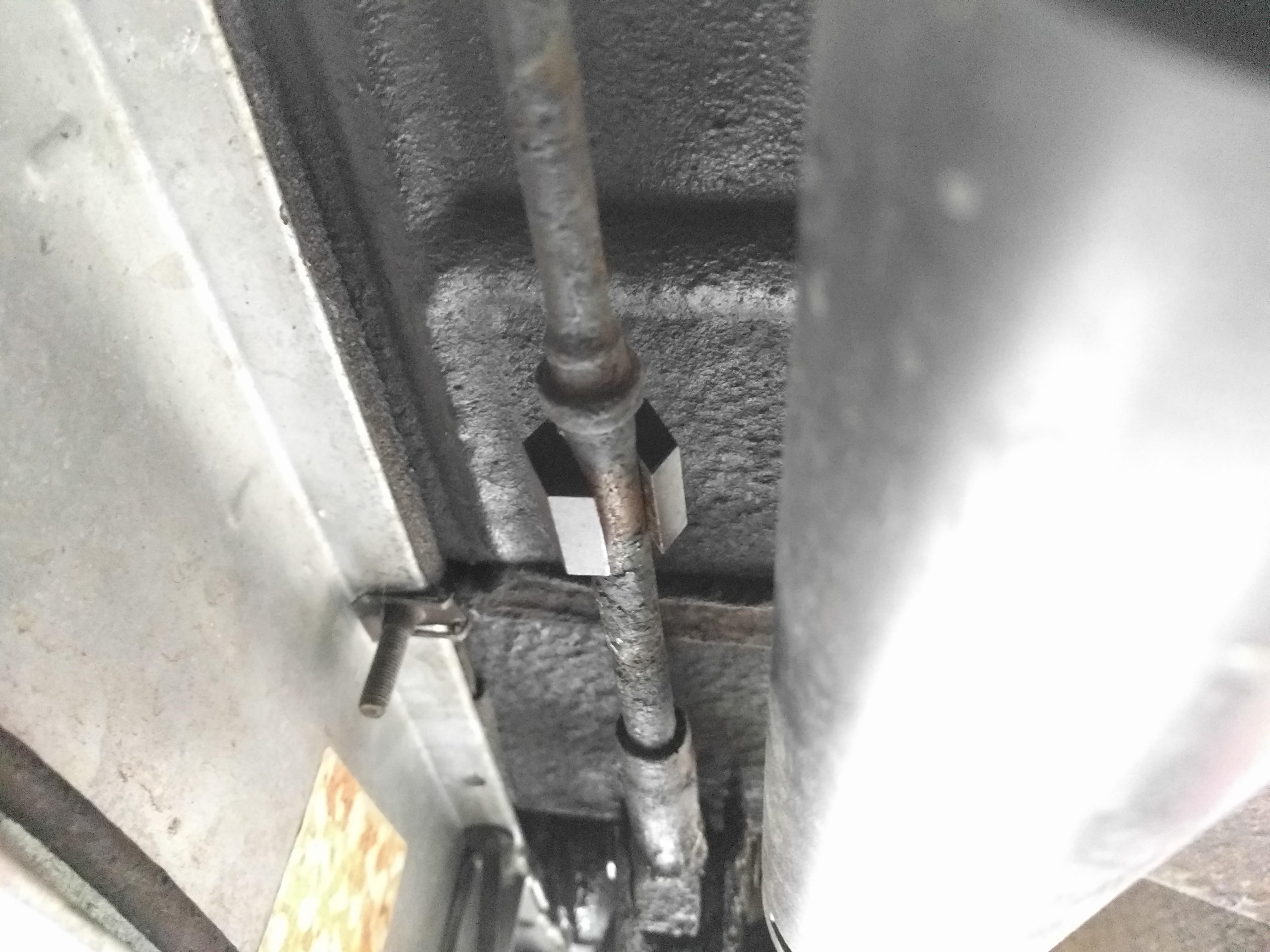
To adjust the ride height the tie rods need to be screwed into, or out of, the eyes that connect to the suspension arms via the knife edges. To facilitate this, the tie rods have 9mm flats on them. Whilst you can use a 9mm spanner you need the shock absorbers off in order to address the flat – which is what we did when we were putting it back together after changing the chassis. The right tool for the job is a 22m hex that has a 9mm slot cut in it.

Whilst access to the tie rods is still a bit restricted, with the adapter on the tie rods the 22m spanner can address it in 12 possible ways which, whilst a bit fiddly, is adequate for the job.
Ensure the tire pressures are correct and the car is unladen (except 5l of fuel if you’re being precise). Using the appropriate wooden measuring stick you can see how far off the ride height is. Then, with one side of the car jacked up to take the weight off the suspension and hence the tie rods, you can screw the tie rods in to raise the car or out to lower the car – a rule of thumb is one turn of the tie rods is about 5mm. After making an adjustment, let the car sit back down on the suspension, give it a bounce to settle it, and re-measure. Then, if needed, jack up and re-adjust. As I needed to raise Judith I put a bit of WD40 on the tie rods where they entered the eyes as that made them a bit easier to turn.
When you’re done the wooden sticks should just fit under the chassis between the axle bolts.

On Sheriff Muir a few miles North East of Dunblaine there is a section of reinforced concrete wall in the middle of the moorland visible from the road.

It was built to emulate a sea wall with a characteristic overhang on the road or “seaward” side and an anti-tank ditch at the base. The front face is pockmarked with numerous impact craters characteristic of shell fire. Significant sections have the facing completely broken away down to the thinner (1/2″) reinforcing rods. Larger (1″) reinforcing rods from the core are also visible in places.

The Northern end of the wall is three meters thick but at the Southern end it steps down to a final width of about one meter. I assume these different thicknesses were to assess the effect of shell fire on different thicknesses of concrete found on sea walls.

In the three meter section there are several significant partial breaches in the structure, probably as a result of demolitions charges – possibly from the Churchill AVRE 290mm petard mortar with it’s “flying dustbin” 12kg demolition charge. These breaches are adequate for infantry to be able to cross the obstacle.

The northernmost of these is a full breach of the wall that’s 4m wide – enough for a Churchill or Sherman to pass through.

On the “landward” side there are large pieces of concrete that have been deposited some distance back from the wall which suggests a significant quantity of explosives were employed.

Being a relatively short section of wall, and with the various thicknesses, it’s unlikely this was used for troop training. The most likely explanation seems to be that this was used for testing the effects of different artillery shells and engineering equipment on a section of sea wall similar to that found at the landing beaches.
Several hundred meters to the South there is a blockhouse which I went back to explore later.
As the hop has started growing the stems have fairly quickly reached the point where they need support.
There had been a satellite dish on the side of the house above where the hop planter is now so I was able to re-use a couple of the mounting points for that to put up a wood batten into which I had screwed four eyelets with long stems to hold them clear of the wall.

I also added four eyelets to the inside of the planter and then ran coir string between them using clove hitches to tie it off.

The coir string is good for climbers as it has a rough texture that gives them plenty to take hold of. Rather than the tendrils used by peas and beans the hop stems have very small hooks on the stems that feel almost like velcro and it’s these that hold them onto the strings.

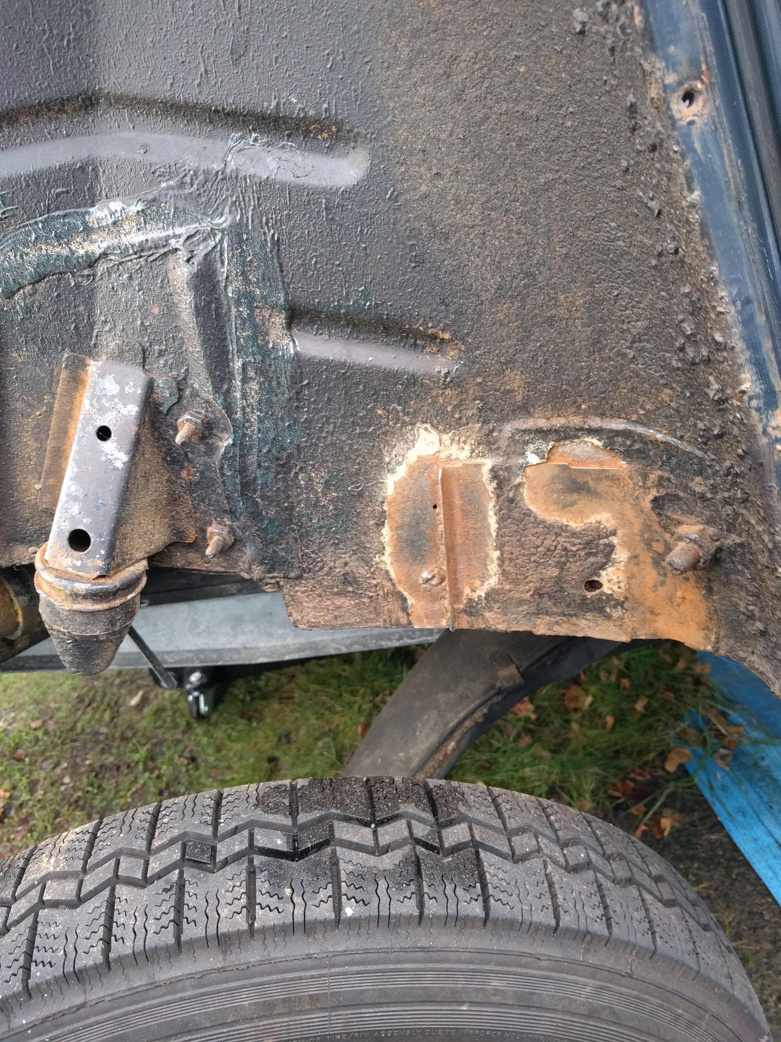
The rust proofing – or rather lack thereof – that came from the Citroen factory is well known to 2CV owners and mine was no exception. One of the areas that this manifests is the rear wheel arches as they’re hard to get to with the wings on and they get whatever’s on the road effectively deposited over them by the rear wheels. When we changed the chassis I had a look at them and there was a suspiciously iron oxide tinge to some of the mud brown so I put this job on my list.
With the rear wings off the wheel arches are easy to work on. The first step was a thorough clean of the clart to see what was going on. Mostly the surface was OK and the paint, although not great quality, was still holding. There was still some underseal in evidence but not uniform as evidenced by the areas of surface rust. The main areas were the bump stop mountings and the seat belt reinforcement panels (that had been replaced in 2004).

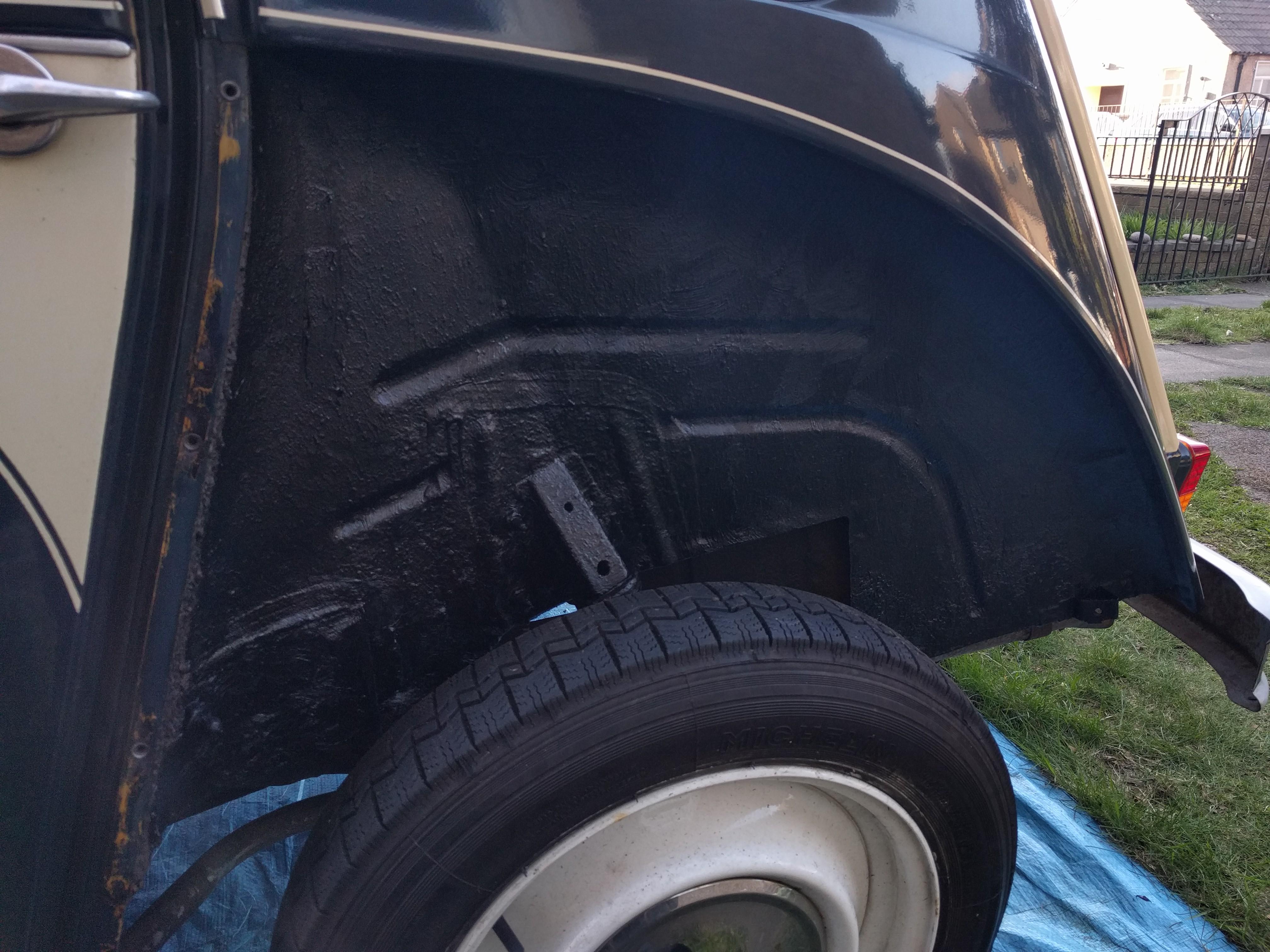
Treatment for this was a wire brush in a drill to take it back to good metal followed by rust remedy. A top coat of blue hammerite finished it off, this turned out to be much lighter blue than I was anticipating but it’s in an area that doesn’t show, will be covered in underseal and when the rust returns I’ll be able to see if it’s in a new area or the same place which would indicate a deeper problem.


With the rust treated it was time for a decent coat of underseal, not very pleasant stuff to work with but when it’s been warmed up it at least goes on easy enough.

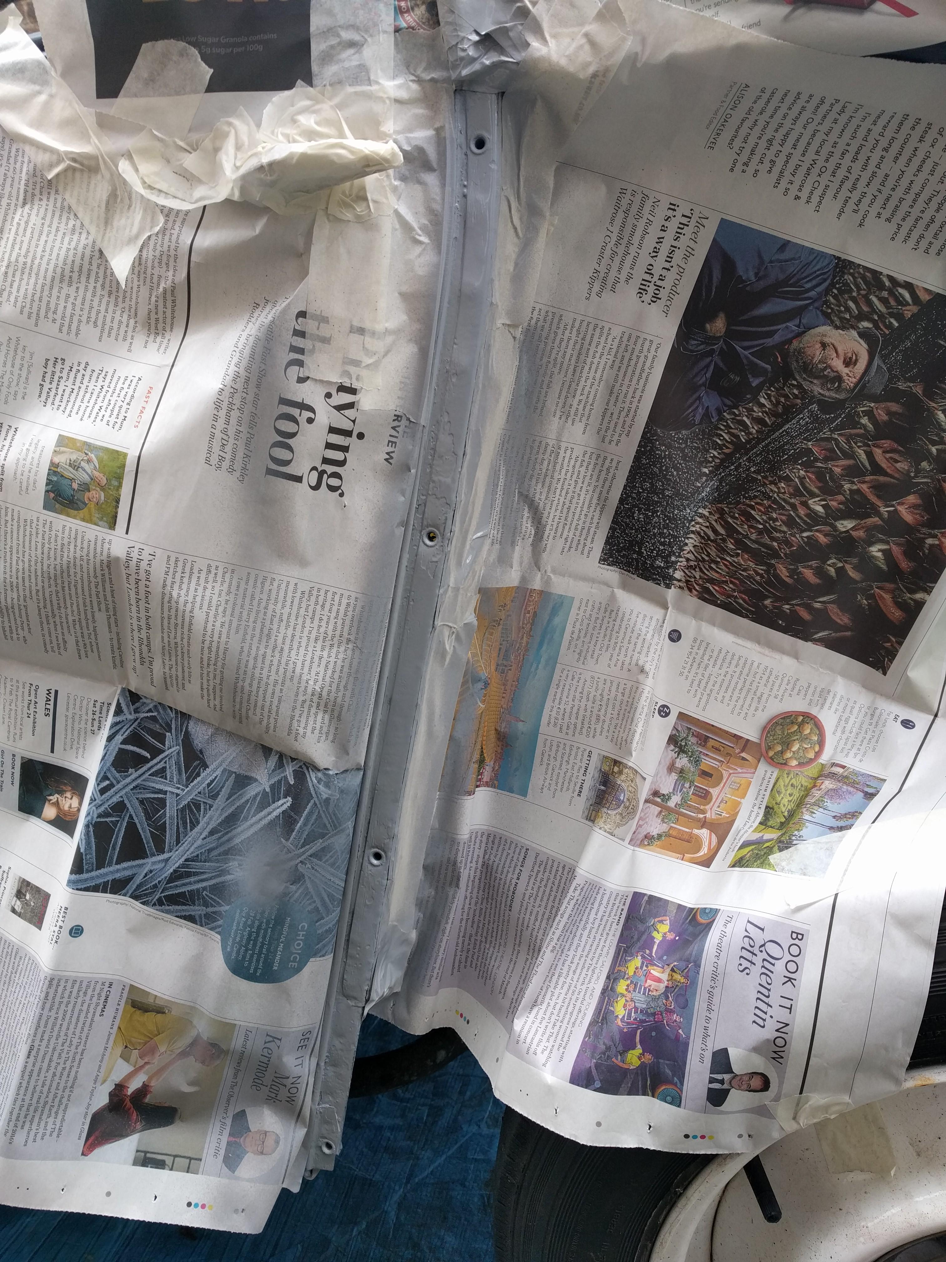
The final part was the leading edges where the wings are affixed. There were a few places where the tin worm had established colonies so these were attacked with the wire brush followed by rust remedy. After some creative masking they were treated to etch primer, primer and two top coats.
With all of that done, this area is now much better protected than when it left the factory, hopefully that should put a crimp in the style of the tin worm which was close to getting established in places.


We have a space by the back door that’s south facing and an ideal spot for a climber. Being from Kent I decided to try and see if I could grow a hop in this spot. As a bonus I found a nursery that sells hops a few miles up the valley from where I grew up.

Hops are a rhizome so need space for the roots, from what I’ve read they will grow in containers – provided they are big enough. As this is by the access to the back door space was at a premium so I got two narrow planters, took the bottom off one, and fixed them on top of each other to create more volume. Growing in a container will probably dwarf them and reduce the crop but as I don’t want it growing onto the roof of the house and as I’ve selected an ornamental variety I think it’ll be fine.
The hop comes as a bare root wrapped in moss for protection.

The planter was lined with a bin bag to help protect the wood and the bottom half was filled with topsoil I had for the lawn and the top half with garden centre compost. Then I hollowed out a space for the roots and filled that with compost from the bin.

Following the hop planting guide, the crown is below the surface of the soil which was then well soaked from the rain water butt.
Now to wait until around April when it should start sending up shoots.

Of the four variants of 2CV grills the third (number 3) is my favourite – this is the three bar aluminium version (1965-1974). As the bonnet opening was the same shape for grills number 2 to 4 was the same they are interchangeable and the plastic number 4 grill on Judith was broken I picked up reproduction number 3 grill to replace it.

After taking off the old grill, the mesh stone shield that sits behind it and the numberplate I was faced with the old enemy: iron oxide. Round the edges of the bonnet opening the paint had been chipped, the numberplate rubs on the central fold of the bonnet and had gone back through the wafer thin paint, and the mesh was starting to pick up some surface rust. There was also a slight dent in the bonnet at the offside top corner of the opening.
Still, an initial dry fit of the new grill looked good.

After a somewhat inexpert bit of panel beating on the dent, a clean-up of the rust, some rust remedy, etch primer on the bare metal and a keying of the old paint, the bonnet opening was ready for a re-spray.

My rattle can technique needs some work as there were a few runs in the paint (holding the can too close and trying to put too much paint on in one go) and it was quite cold so it dried a bit matt. However, it’s going to be hidden behind the grill and numberplate so a good place to practice.

After the paint had been left for at least a week to cure (another learning moment) and the final touch ups had been done (and left to cure) the grill could be fitted.
The plastic number 4 grill clips in but the number 3 needs bolting in at the top: for this I used countersunk, 16mm, M6, stainless, hex socket bolts with nylock nuts and a broad washer. It has two tabs on the bottom that need bending over to secure it against the lower lip of the opening. The mesh had been coated with the trusty satin black and is held in at the top with the new bolts and at the bottom with the original screws and washers. Finally the grill surround needed a bit of gentle bending to conform properly to the bonnet.

The last thing before re-fitting the numberplate was a strip of anti-rub “helecopter” tape down the centre line fold of the bonnet to protect the paint from rubbing off again.

All that’s missing now is a set of chevrons for the bonnet.