With the crank case separated there were a few items that needed removing before they were ready to be cleaned.
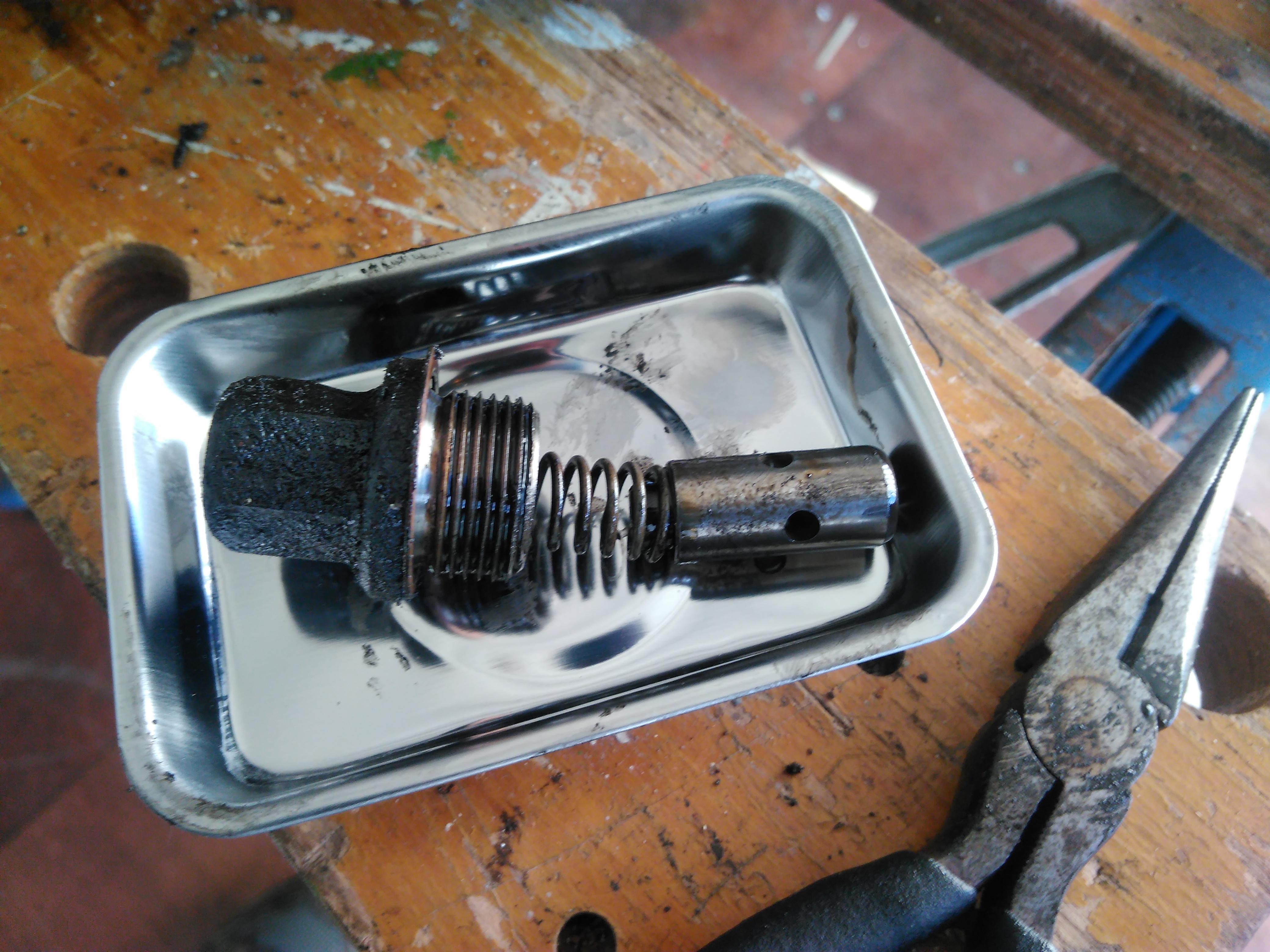
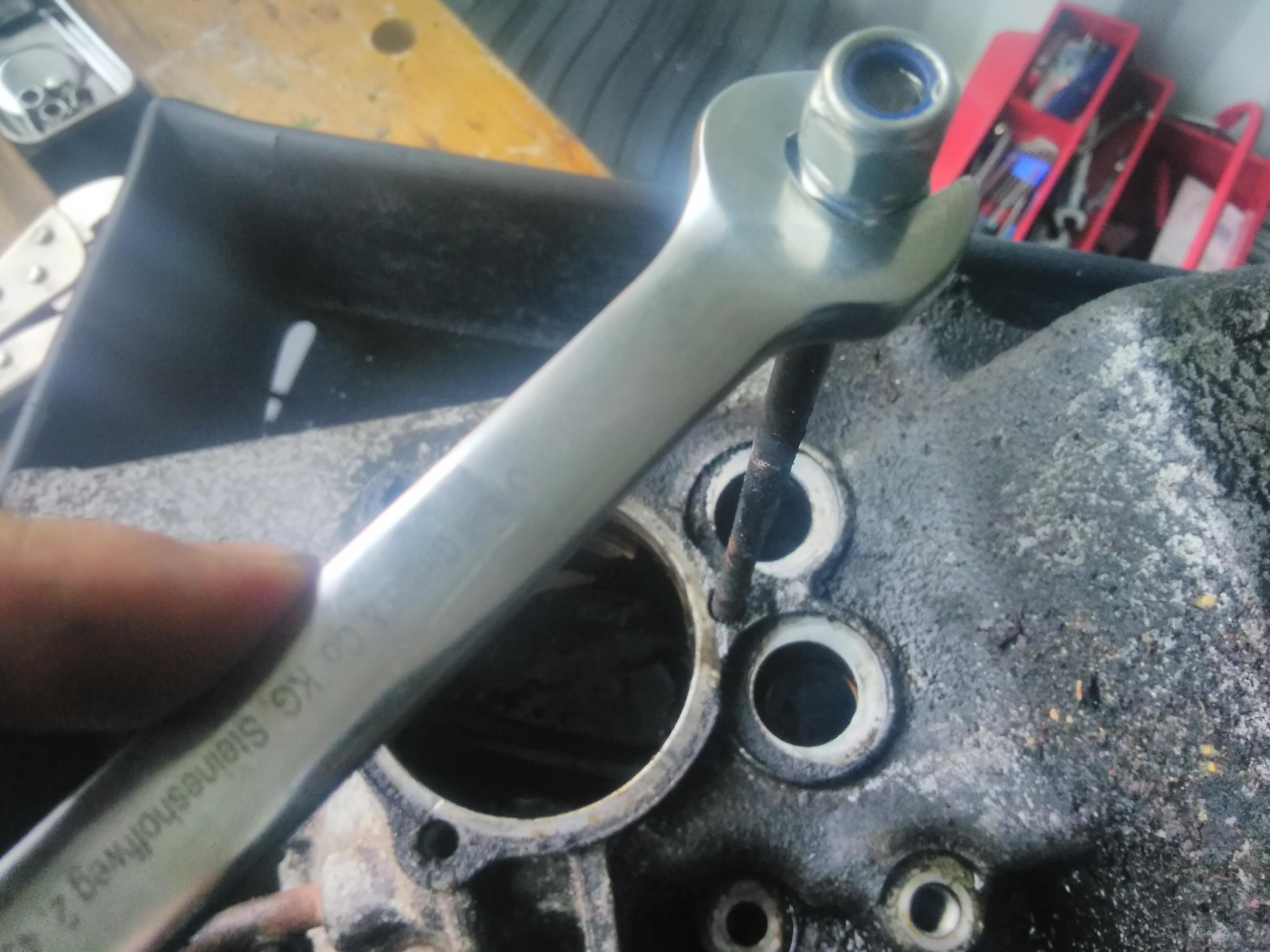
First up, the oil pressure relief valve, this is a big 17mm nut on the off side
Inside there’s a spring and a plunger, which needed extracting with needle nose pliers.
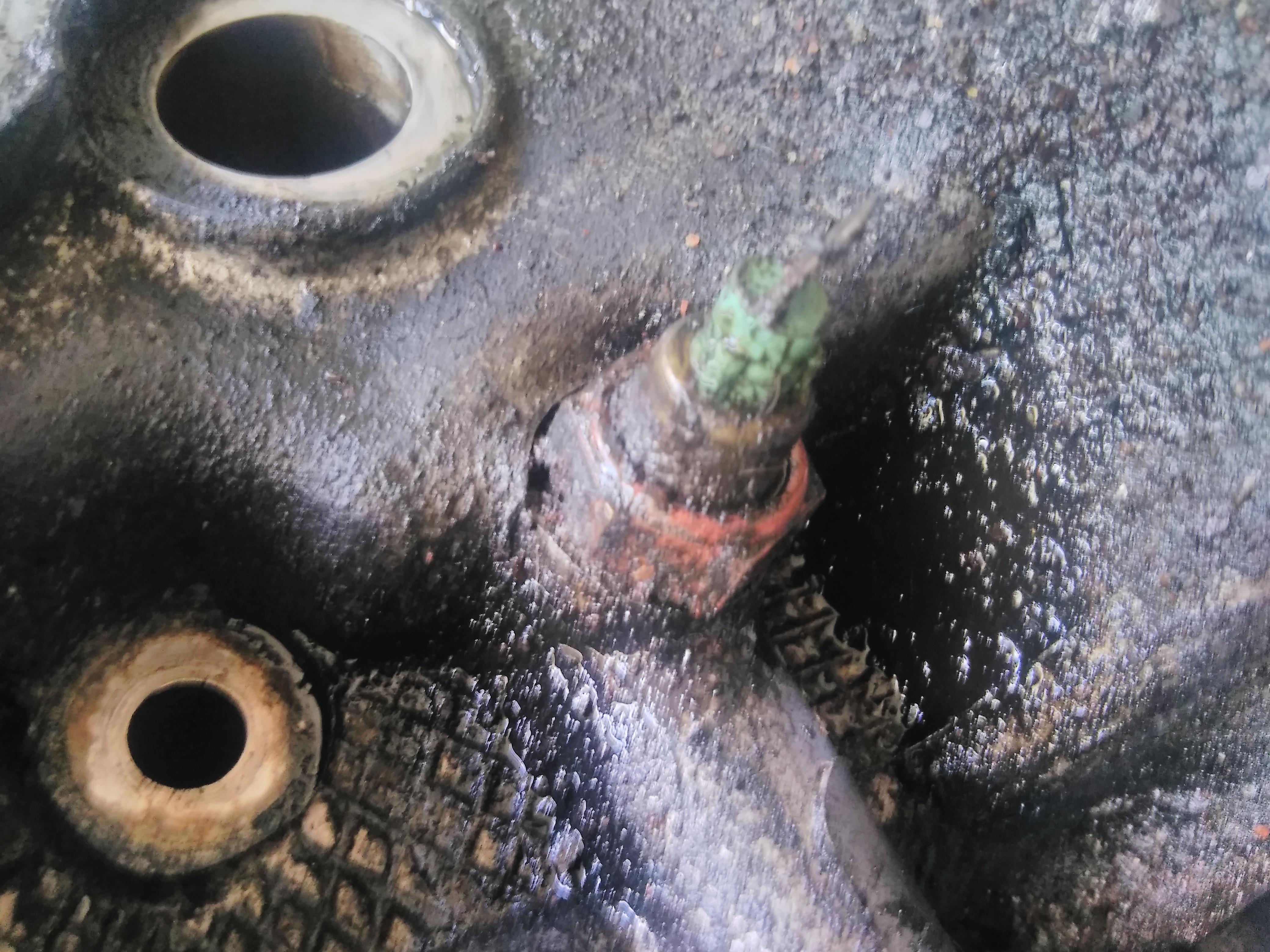
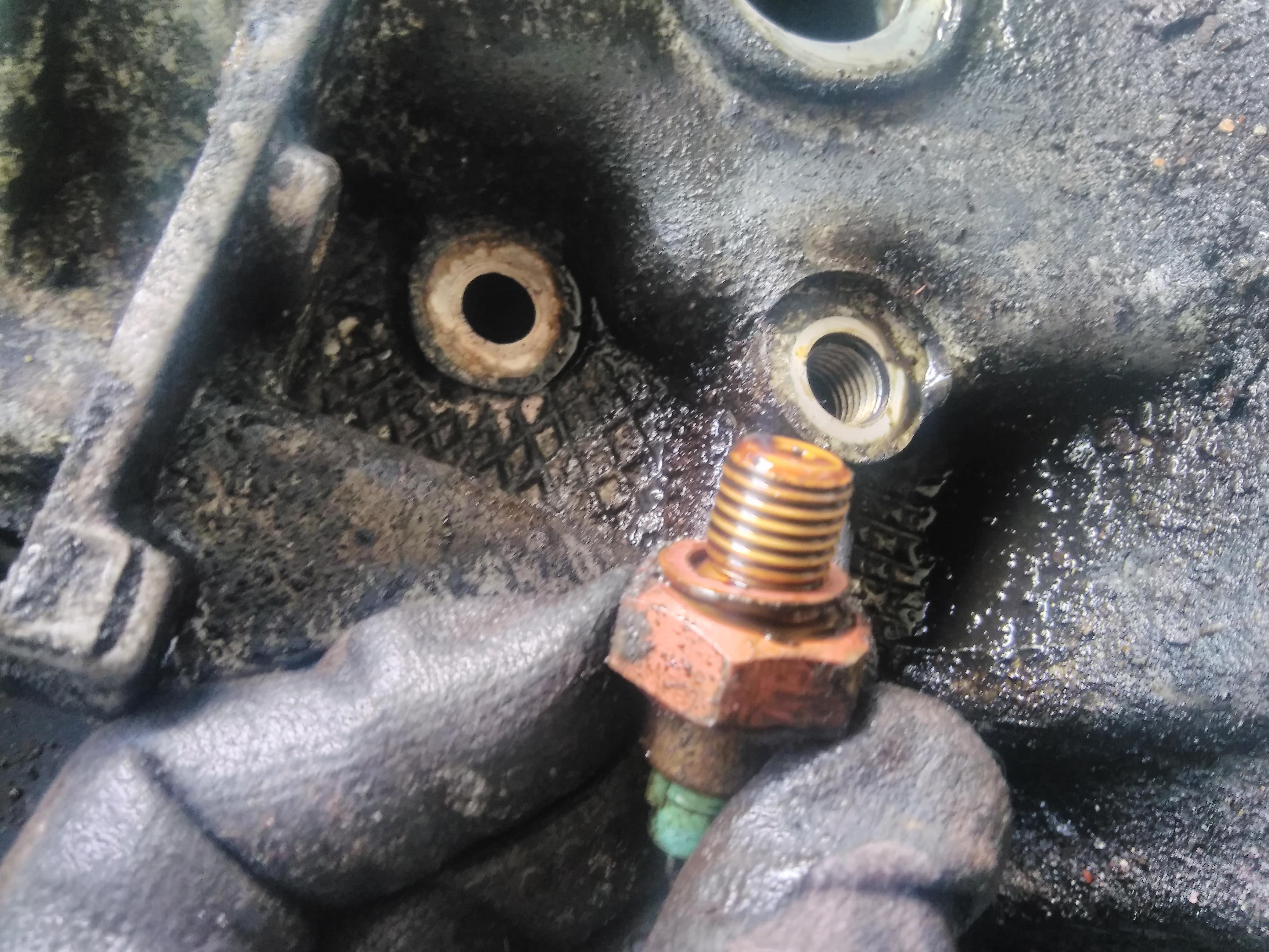
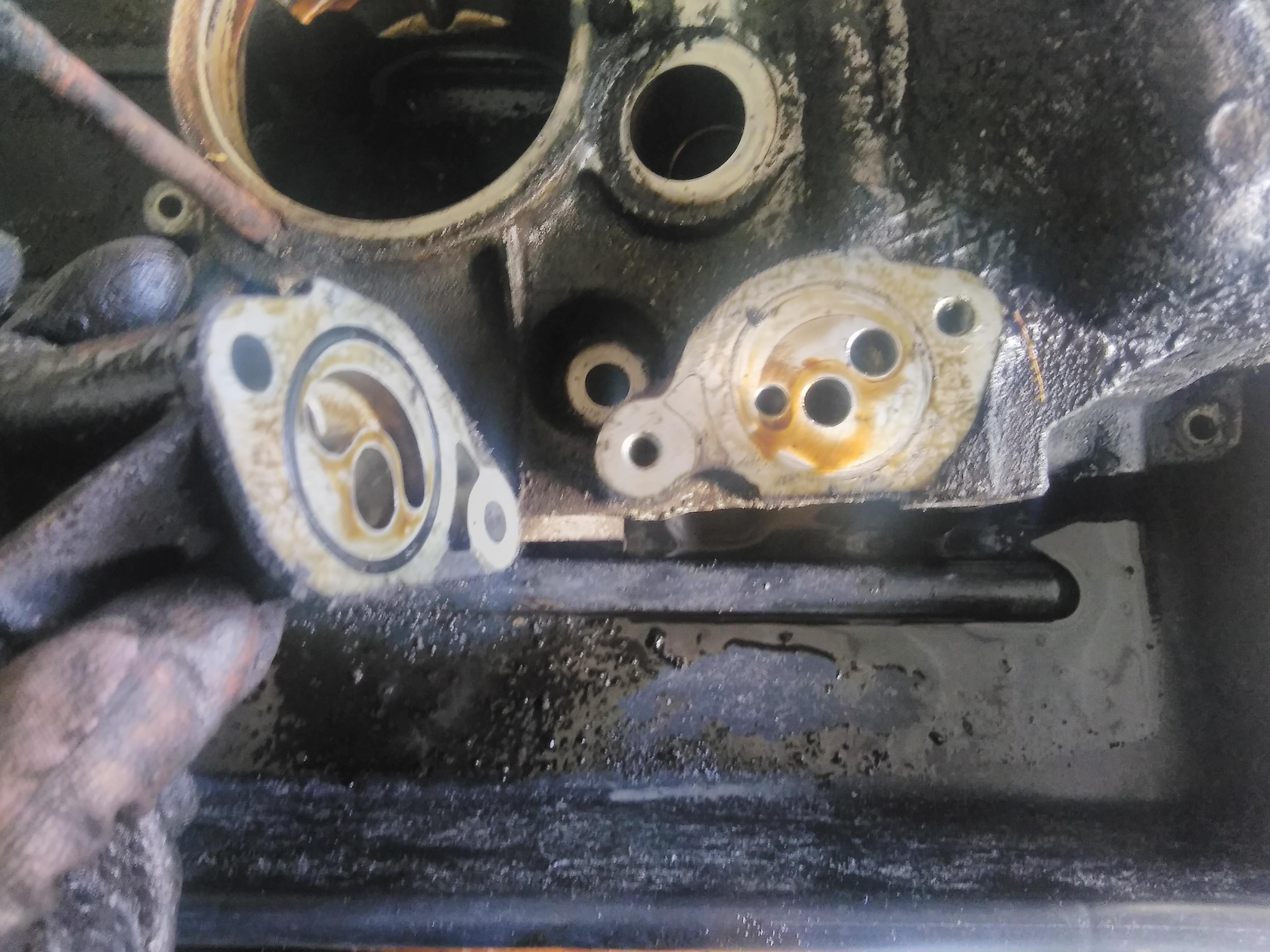
On the other side is the low oil pressure sender.
In the front there’s some rubber seals for the oil cooler unions.
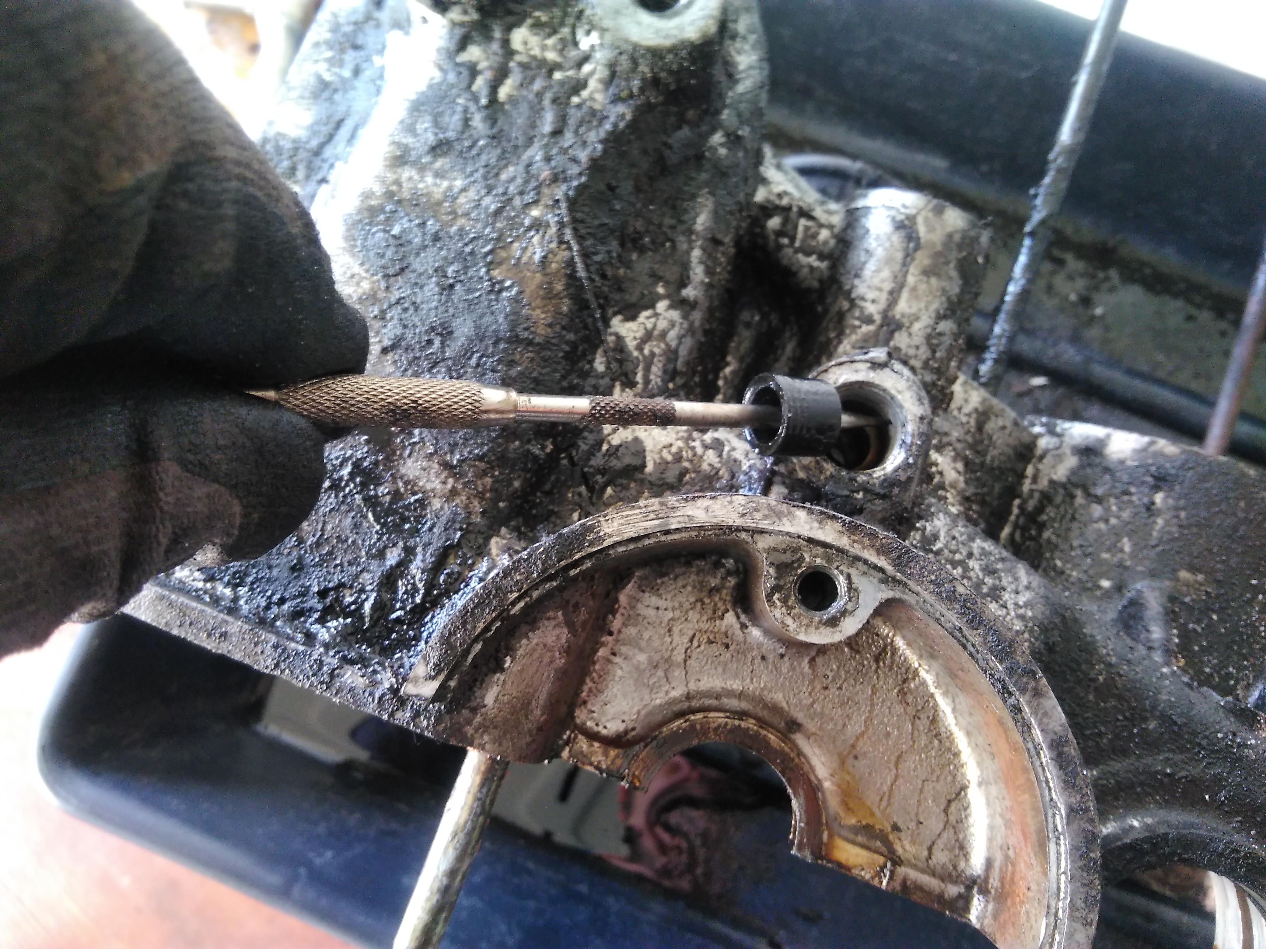
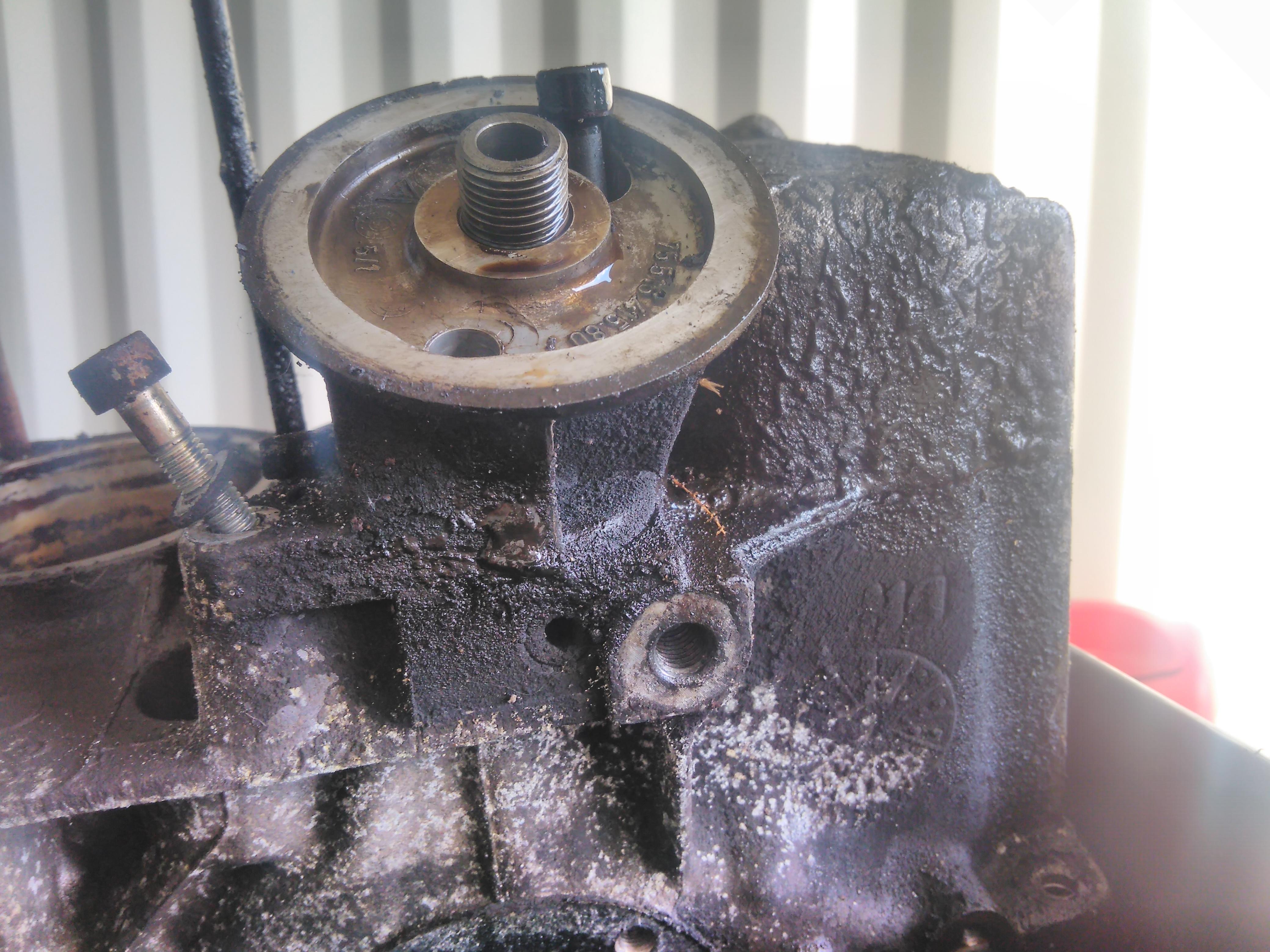
The oil filter mounting plate is held on with two alan bolts, one inside the filter mating surface and one at the top of the plate.
There is a rubber o-ring seal in the bottom of the plate where it mates with the crank case.
The head studs are a bit awkward but the standard stud extraction technique of a pair of nuts clamped onto each other should provide enough purchase to get them moving.
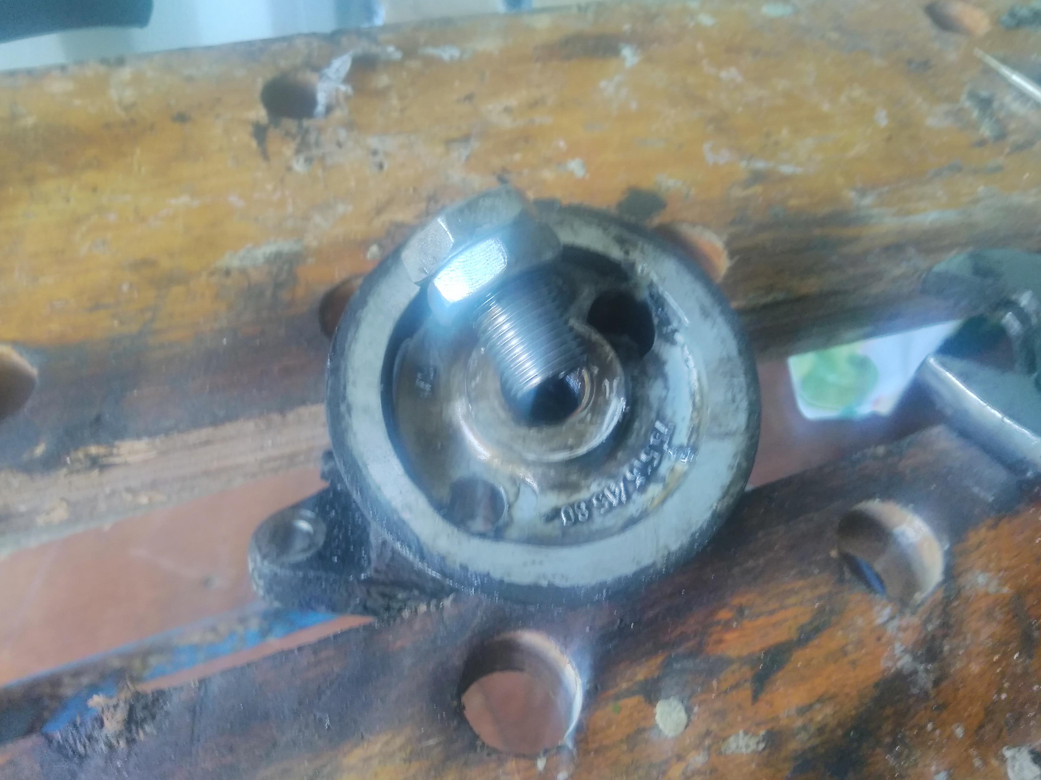
As part of the rebuild I’m fitting the SPOG oil filter adaptor, this allows the use of the more common 3/4″ 16 UNF threaded oil filters. The kit comes with a a pair of nuts that fit the M16 thread on the old spigot and, using the same technique as for the head stud removal, it unscrews.
The new SPOG spigot has the smaller M16 thread on the lower half so it fits back into the mounting plate but the larger 3/4″ 16 UNF thread on the upper to attach the oil filter.
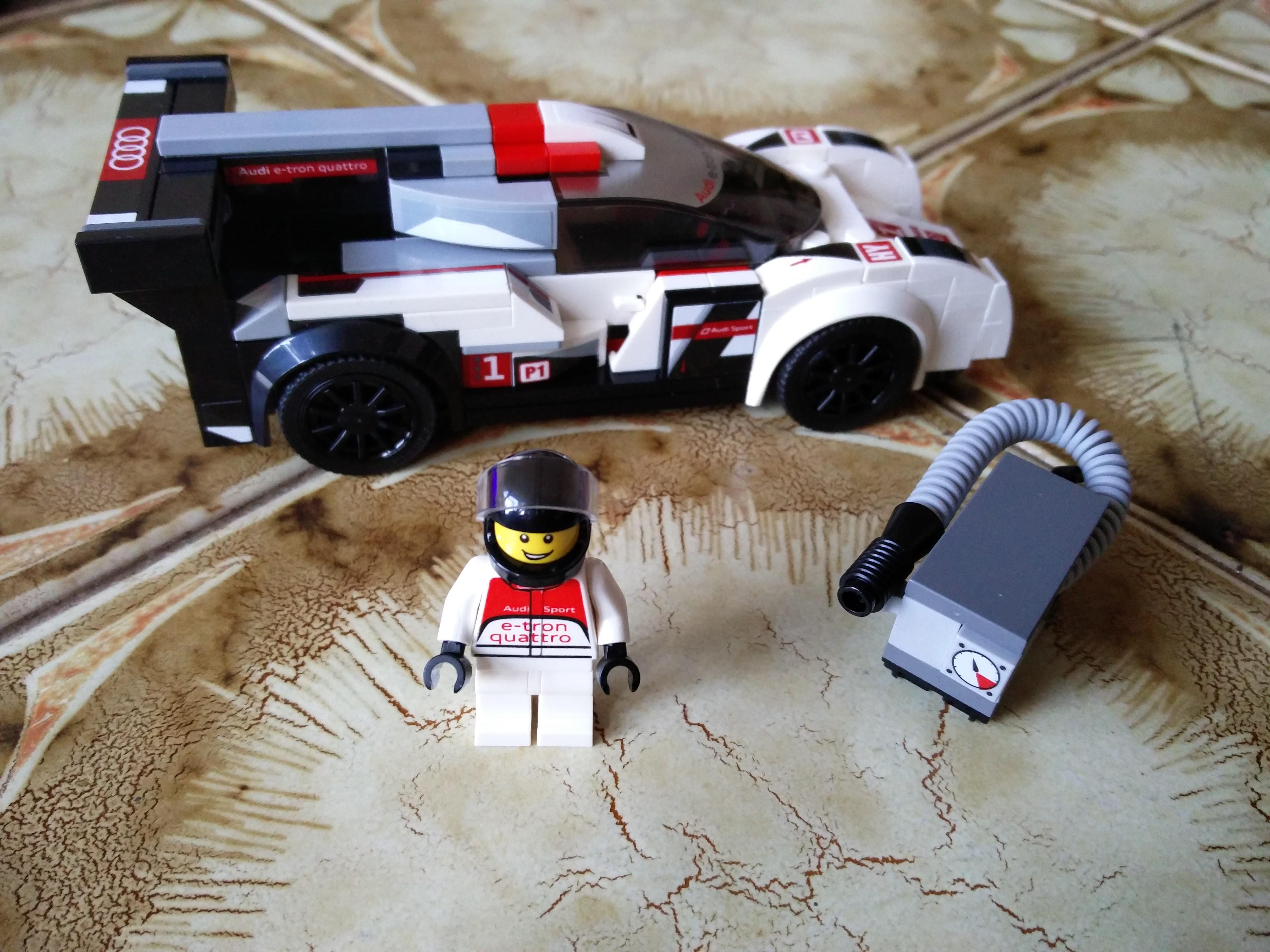
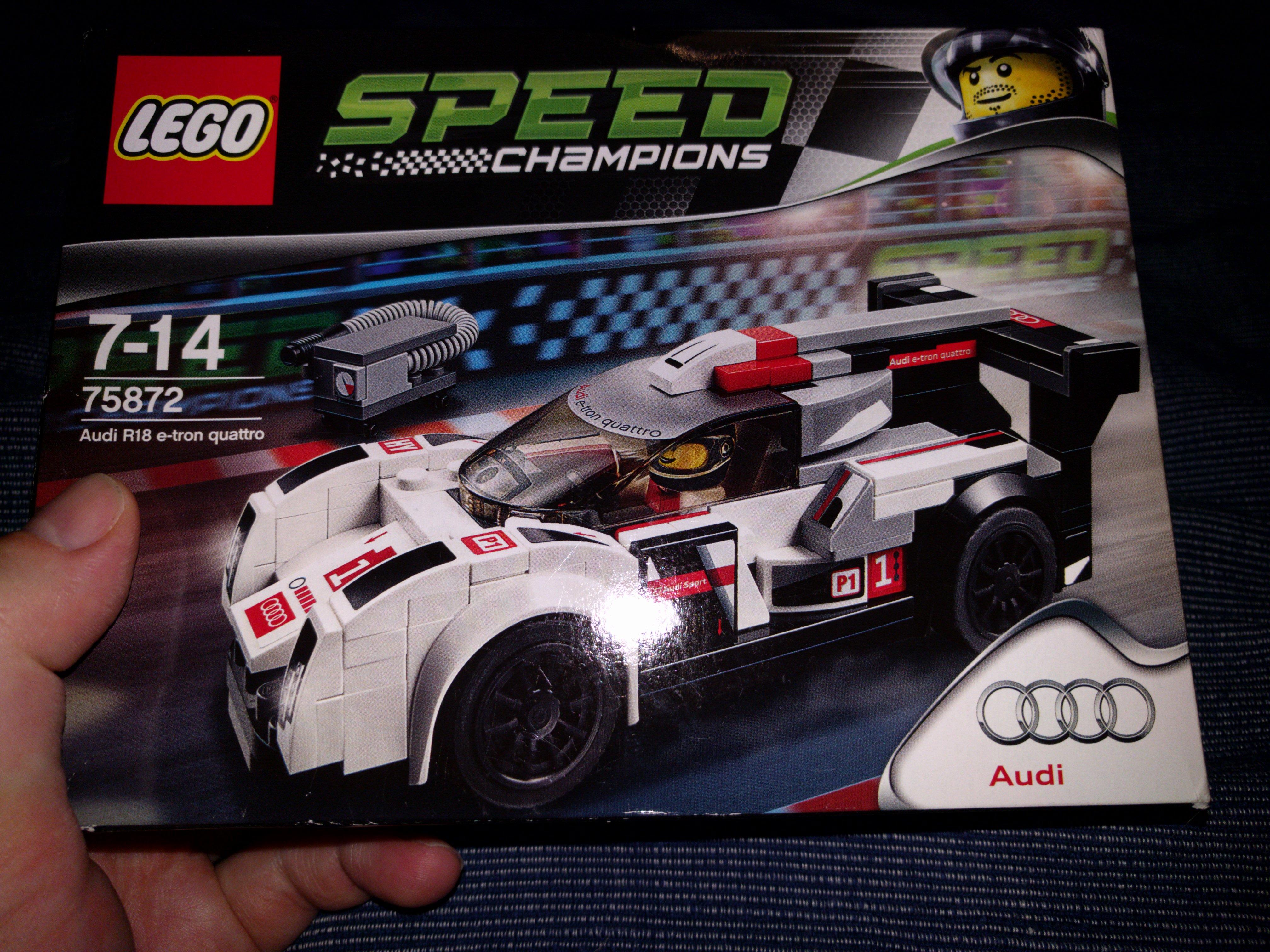
Additional displacement has arrived from ECAS in the form of a Burton 652cc big bore kit. This ups the compression ratio from 8.5:1 to 9:1 and adds 25cc to each cylinder (an extra 8%) which should produce both more power and more torque*. Roy at ECAS recommended that a race profile cam from Kent Cams would be a good match for this as the extra breathing the cam provides will be matched by the larger displacement – all providing the fan and tinware are retained to ensure sufficient cooling.
Burton’s bench test shows an increase in torque from 6 to 7 but I can’t work out what the units are :-/
This film shows how to disassemble and assemble a Citroën 2CV engine quickly. The movie is made as an instruction for the ‘engine battle’, that we held at the AutoRai 2015. In the battle, people competed against each other assembling an engine.
This movie can be used as a guide when you’re rebuilding an engine, but be advised; some parts are skipped and missing for the purpose of the Discovery Channel engine battle instruction (for example; no liquid gasket material was used on the crankcase halves of the engine).
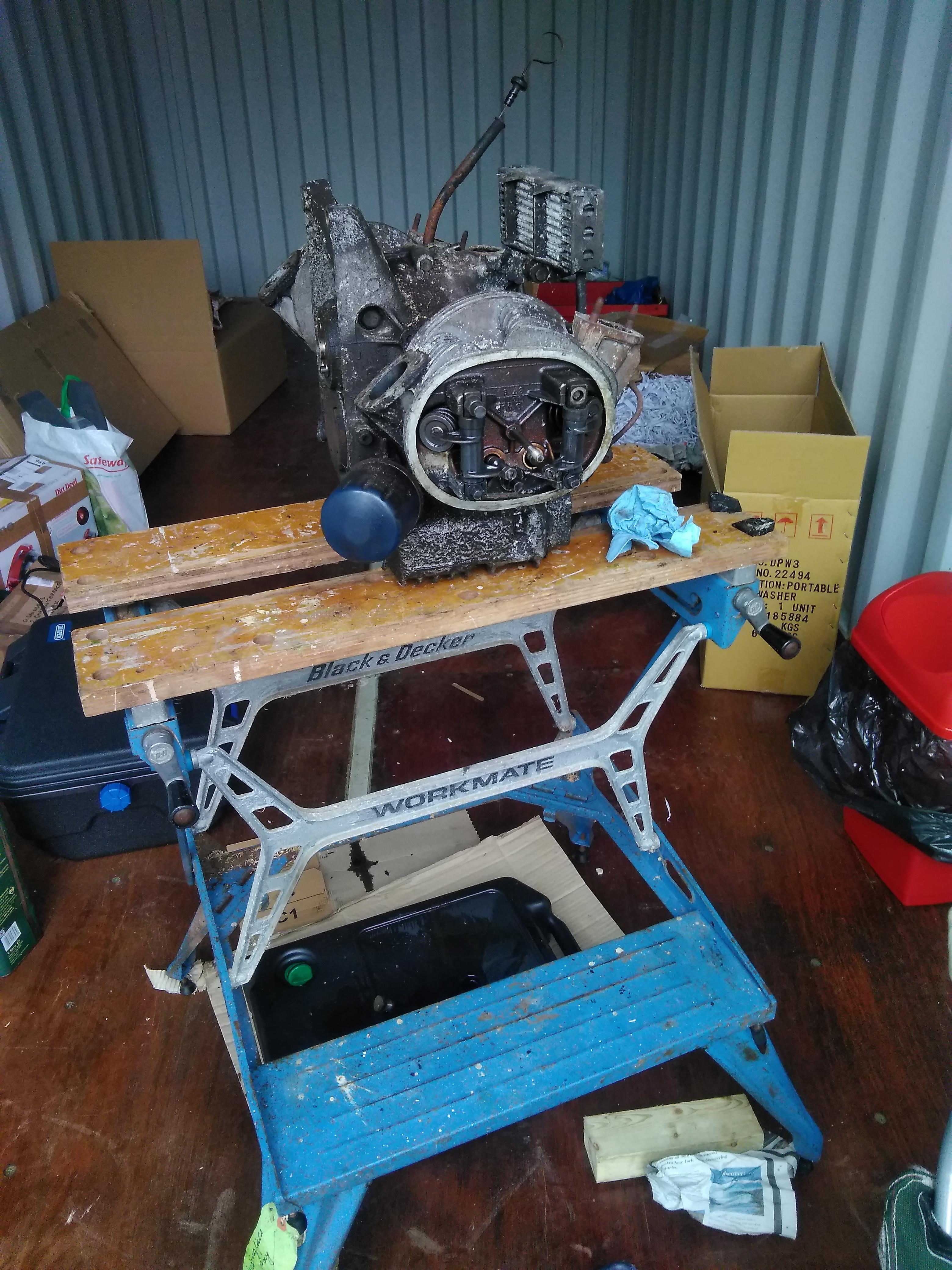
After removing some of the external ancillaries such as the fuel pump and the flywheel (with the assistance of Super Crack Ultra, heat, an impact wrench and a breaker bar) and leaving the oil to drain I got stuck into dismantling the engine.
Firstly I got the the jelly moulds off to drain the residual oil and reveal the valve gear.
At this point it became clear why the engine wasn’t fully turning over: one of the head studs on the off side cylinder had sheared at the bolt.
As this bolt also secures the rocker pivot axle it meant the exhaust valve wasn’t able to operate fully thus jamming the push rod, thus jamming the camshaft, thus jamming the crank. Fortunately it doesn’t look like any damage has been done to parts I wasn’t planning on replacing anyway.
With the head stud bolts and the oil feed pipes removed, the barrels and heads came away from the crank case. Whilst the near side head and barrel separated by hand the same wasn’t true of the off side (home of the malfunctioning valve) – despite application of my not inconsiderable bulk via a pry bar!
I applied a large libation of penetrating fluids and left it to marinate whilst I moved on to the crank case.
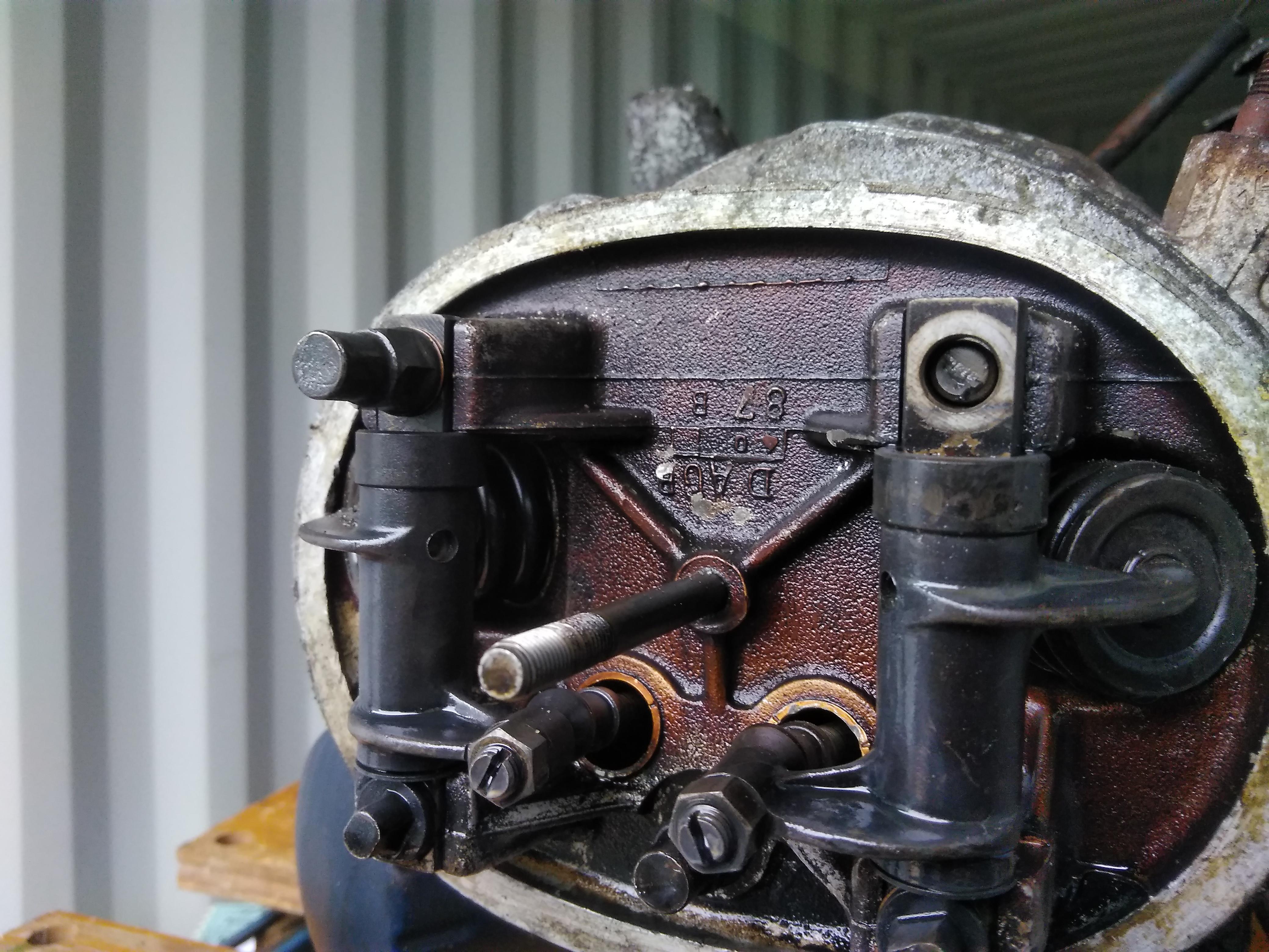
The crank case splits in half down the vertical longitudinal axis and is held together by four large (14mm) bolts in the centre and half a dozen smaller (11mm) bolts round the outside. However, there are some items that straddle the join so they need to be removed before starting on the crank case bolts.
The oil cooler needs to come off the front of the engine, firstly remove the retaining bolt above the nose of the crank shaft where the fan mounts. Then carefully remove the union bolts and ease the pipes out of the crank case.
Round the back there are a set of five 12mm bolts that hold the cap on the oil pump and below that there are two 8mm bolts that hold the oil strainer in place in the sump.
Work round the outside removing the 11mm crank case bolts – some of which are on through nuts and some on studs so make sure you check which one you’re dealing with.
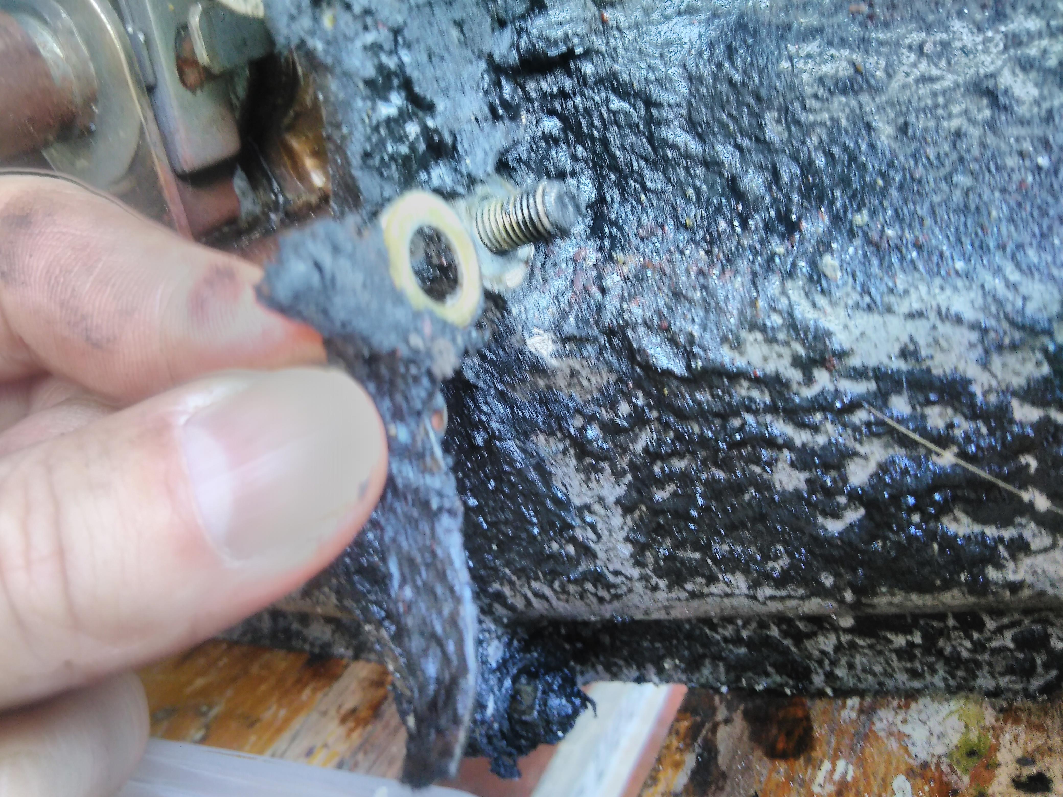
Buried under the surface gunk I found one of the nuts had a washer with a long tab – not sure why but that was the only item of note.
Next up there are the four large bolts, two on each side, that go through next to the crank bearings. With those removed the crank case separates easily.
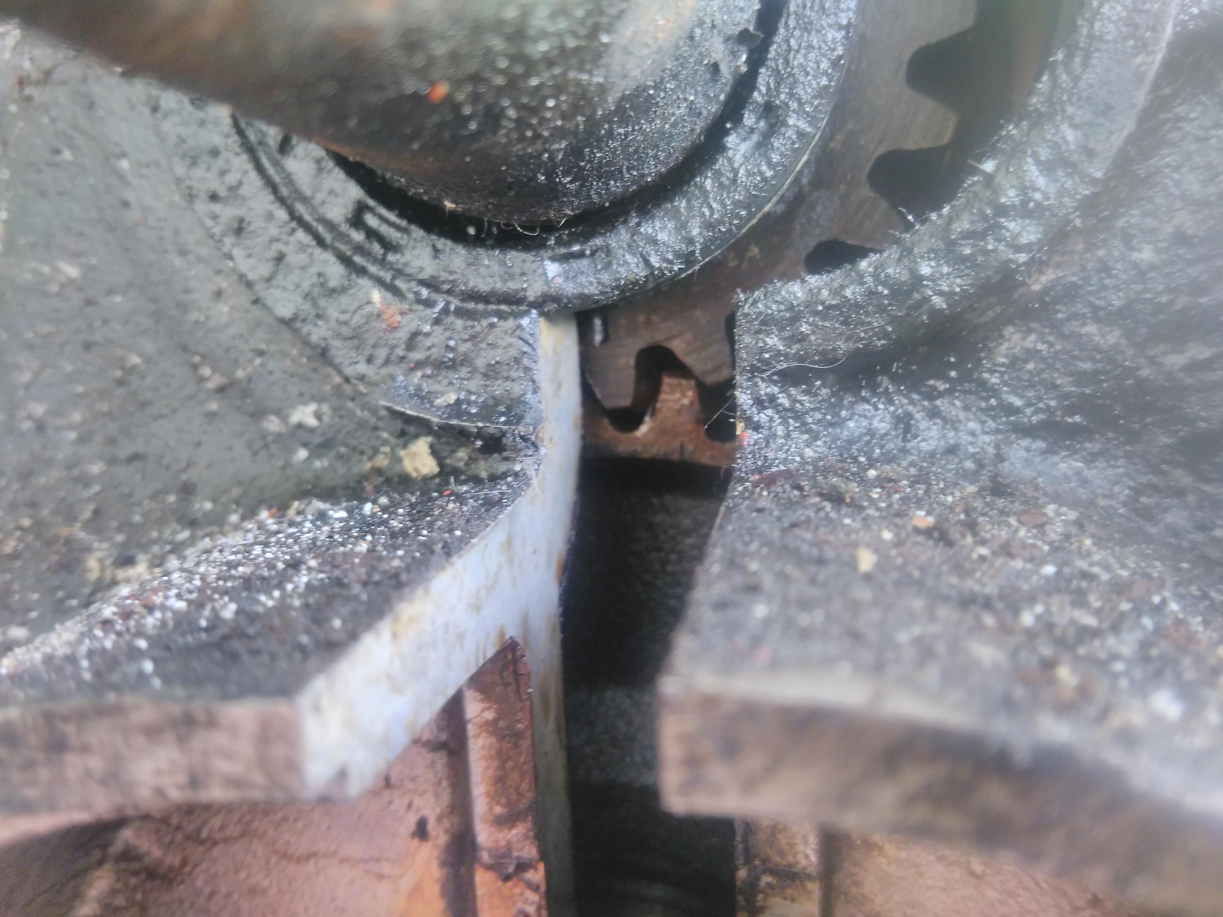
At this point it’s worth rotating the crank and looking out for the timing marks and seeing how they appear when aligned.
The timing marks are small lines marked into the gears under certain teeth. The key one (and easiest to spot) is on the crank and, when at the timing point, it will align with the edge of the crank case half at 6 o’clock.
The timing marks on the camshaft are harder to spot but there are two of them, one on each of the teeth either side of the space into which the crank timing tooth fits.
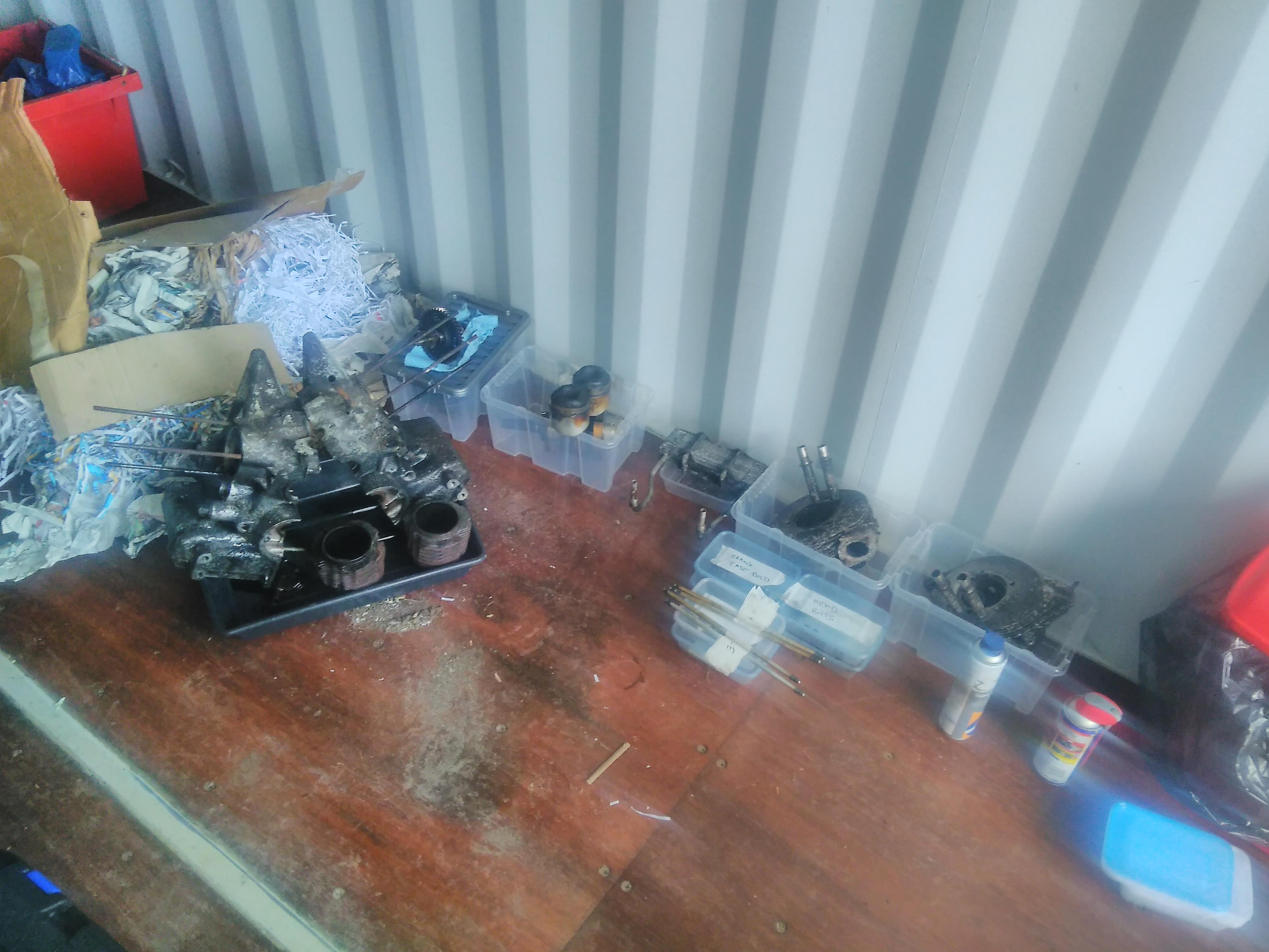
With the crankcase separated the crank and camshaft stay in the off side half and require minimal coaxing to come free.
In the time it had taken to strip the crank case the penetrating fluids had worked their magic on the off side barrel and head and they were reluctantly persuaded to separate.
That’s now the main disassembly complete and with the parts labelled and stashed away in boxes it’s time to call it a day,
We offer a wide range of new and reconditioned carburettors. Both for very early Citroën 2CVs, and for the later 2CV6s. The double barrel carburettors are now available, completely new.
In this short film we like to show you how we test each and every one of them. In our experience all these carbs need a little adjustment to make them work just perfect.