50973
Month: September 2015
Afternoon ride
15:29Down to the Kelpies and picking blackberries. Return of the flying banana.
Roof repairs
11:40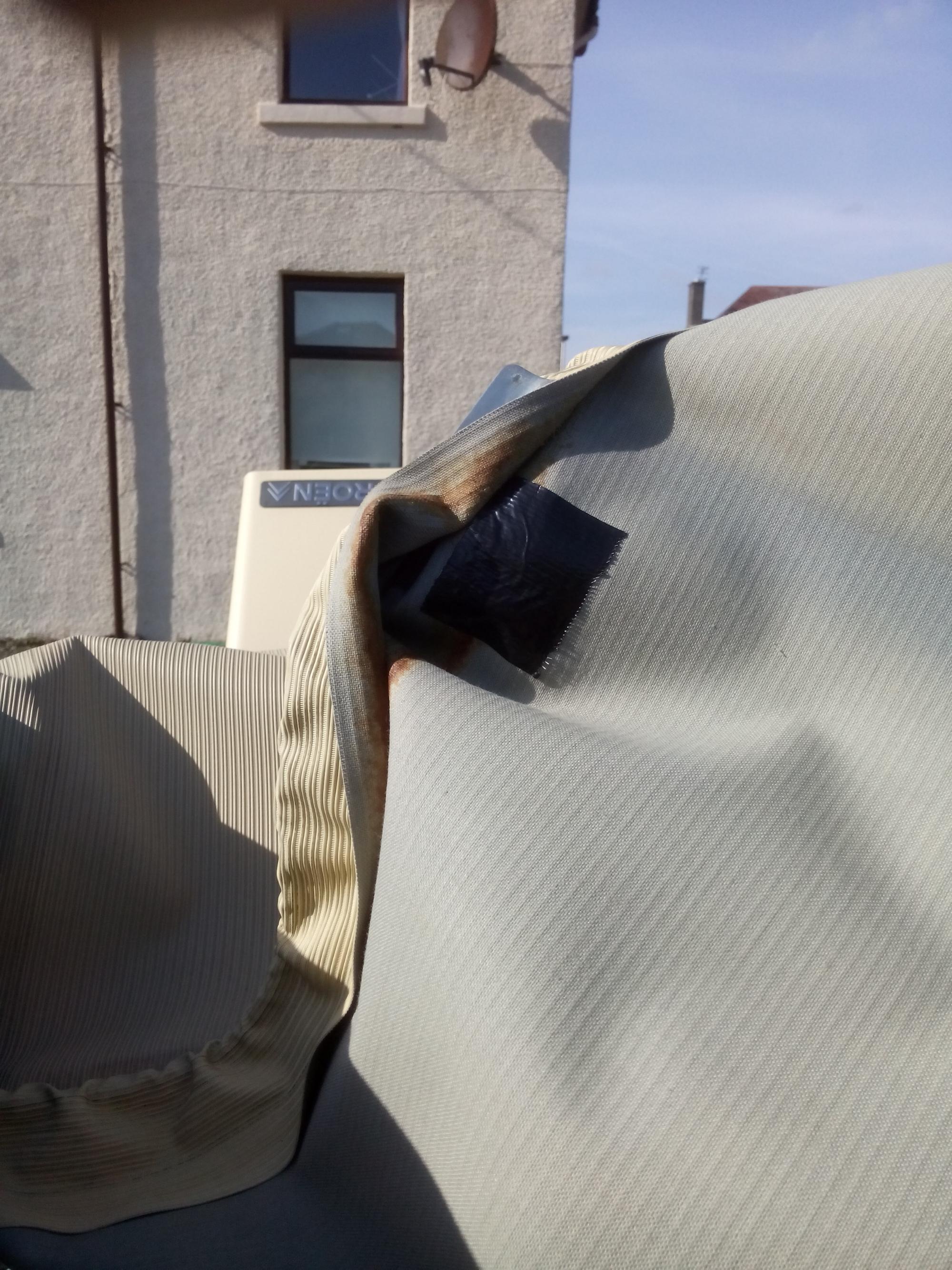
A trip out in the evening sunshine
22nd September 2015 17:54Nothing more, nothing less.
Replaced wiper spindles
19th September 2015 13:26
Setting a 2CV’s ignition timing
15th September 2015 12:14Setting the ignition timing on a 2CV is a routine service item, forming part of the D (anual) service. It will also need doing if the points are replaced or adjusted.
Setting the timing requires the use of a specialist tool – in this case a 6mm rod. I inherited a bent nail which does the job admirably.
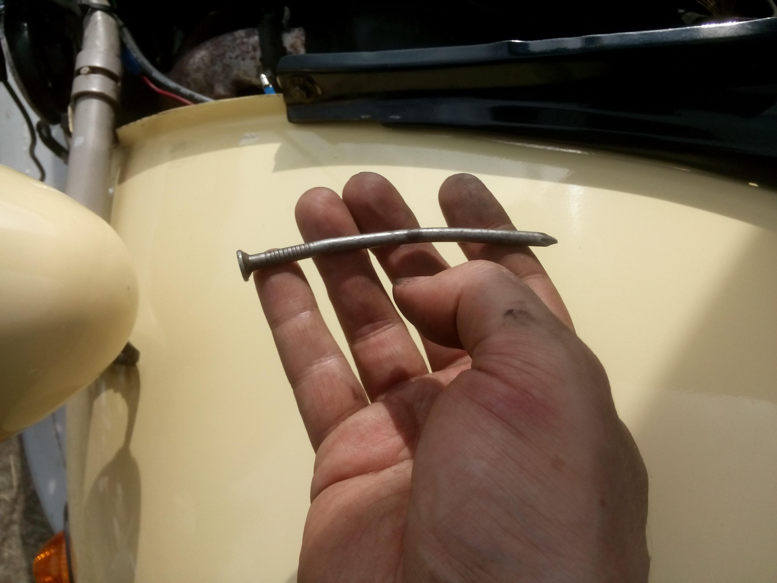
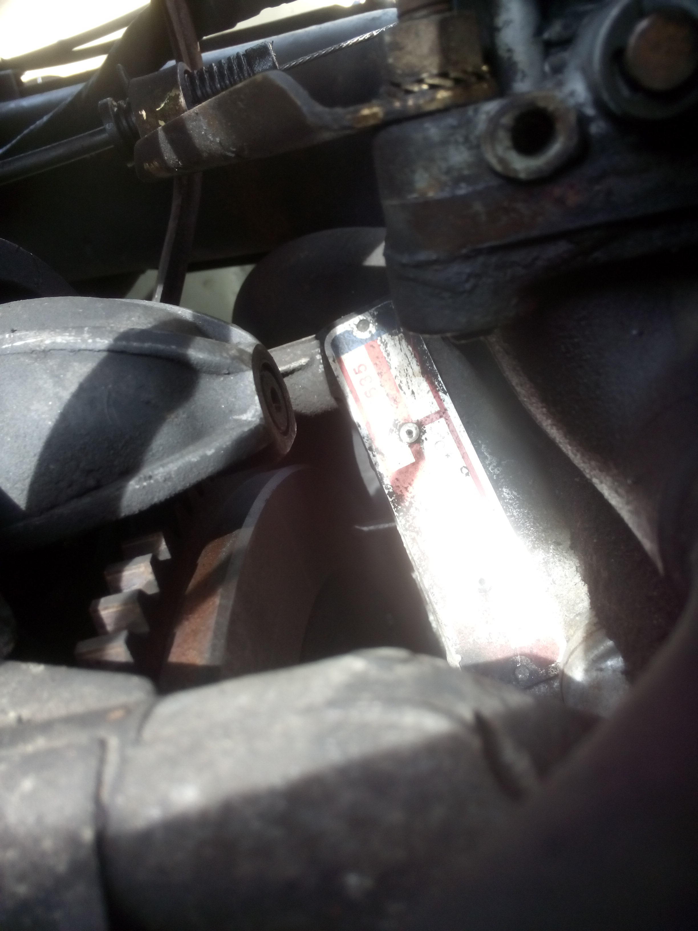
This fits through a hole in the engine block on the near side under the inlet manifold.

The bend in the tool is required as the dipstick tube blocks straight access to the hole. The tool will come out through the hole and present to the face of the flywheel.
Rotating the engine will turn the flywheel until a hole in the body of the wheel will align with the tool. Use the tool to lock the flywheel at the timing point and paint some alignment marks on the flywheel and a static part of the engine. When painting the line don’t forget to take account of parallax.
Now remove the tool – this is important as you will need to rotate the engine to set the timing.
If you haven’t done so already, remove the fan to gain access to the points box. You won’t need to open it for this job.
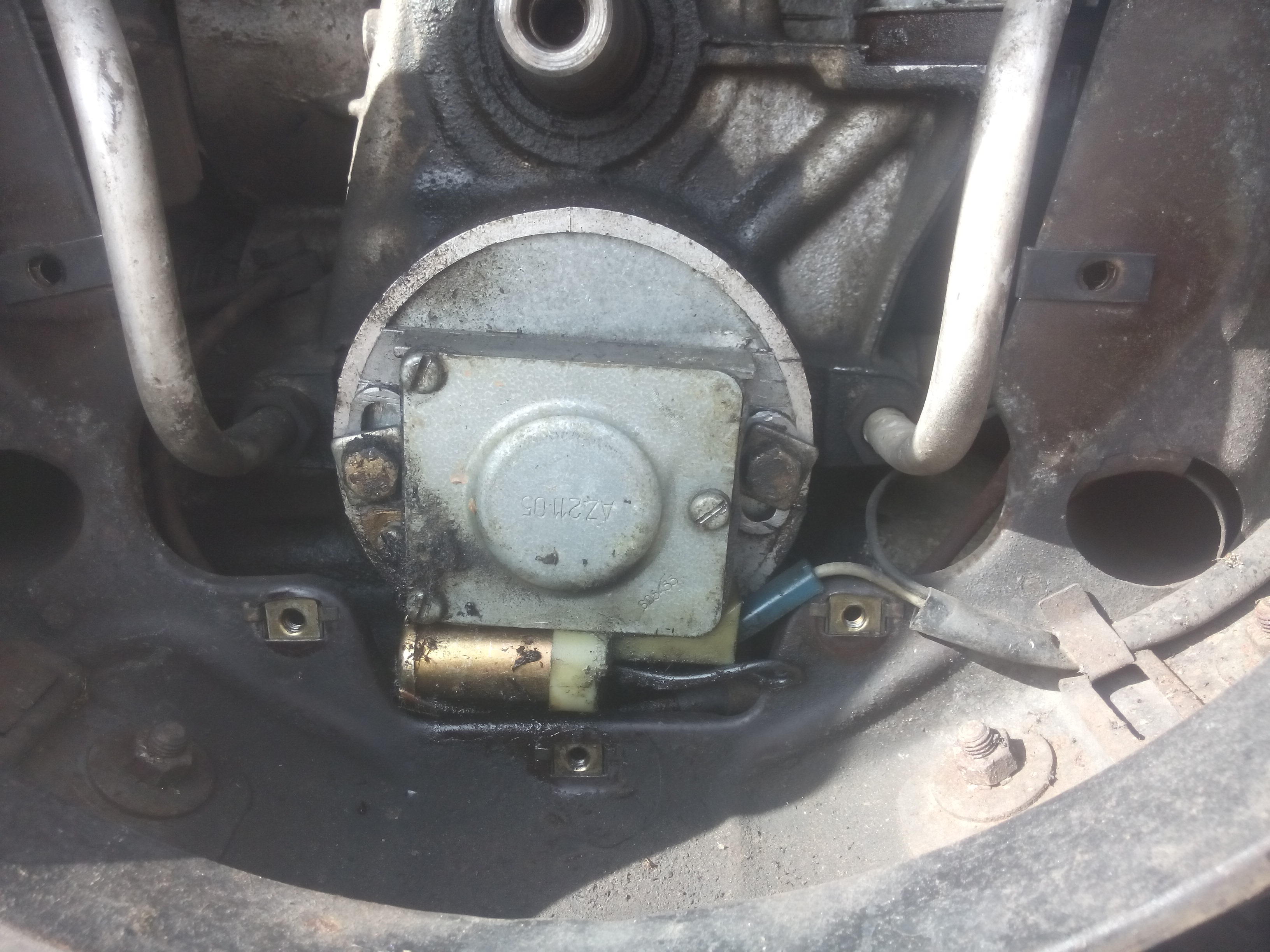
Slacken off the nuts either side of the box and free the box, it might well need a bit of encouragement but be careful you don’t damage the cover behind the points box – it’s relatively thin metal.
With the points box free to rotate connect a test lamp between the positive coil terminal (without fully disconnecting the connector and breaking the circuit) and earth.

It really helps if you can position the indicator lamp where it is visible both whilst you are working on the points box and from above when looking at the flywheel timing mark.
With the flywheel set at the timing mark the light should just come on. Turn the points box back and forth to find the point where the light is coming on and off. With the light just on move to the flywheel and use a large flat head screwdriver to move the flywheel back and forth slightly through the timing point ensuring the light turns on and off exactly at the mark. This should allow you to make the last adjustments to the points box to get the timing as accurate as possible.
Start tightening the points box – taking care not to disturb the position – and rotate the engine to check that the light is still coming on at the timing mark each revolution. Fully secure the points box and make a final check to ensure the timing is still correct.

Replaced wing mirror beading
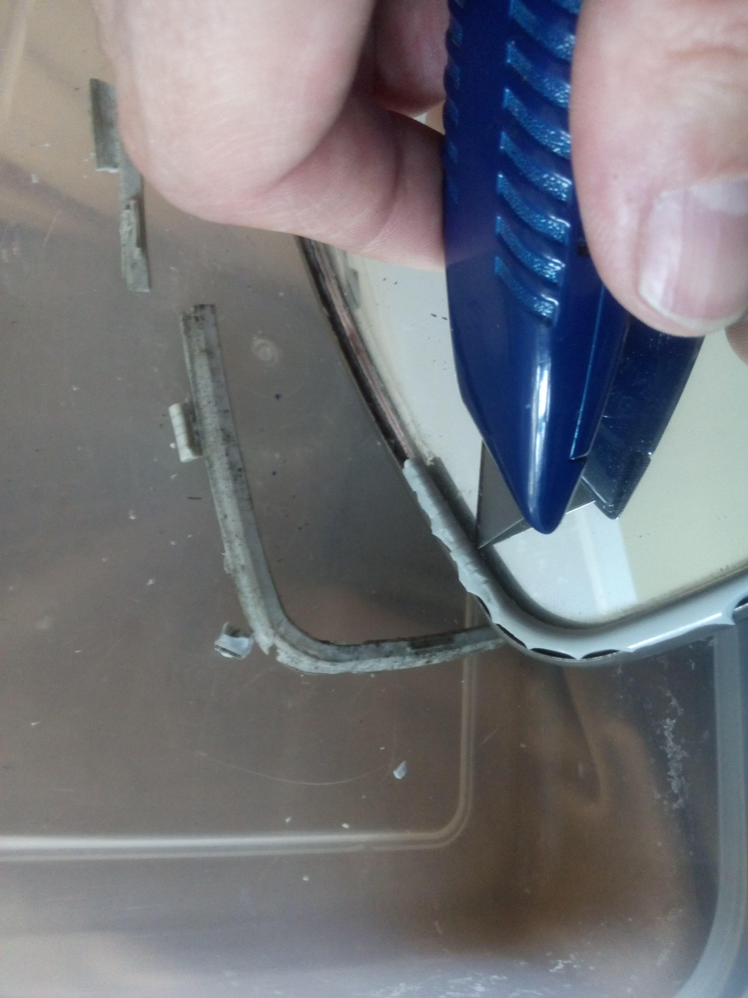
12th September 2015 17:33The plastic beading round a 2CV’s wing mirror is what holds the glass in. Unfortunately the beading on Judith had succumbed to the ravages of time to the point where I had resorted to gaffer tape to prevent it coming out going over a particularly harsh lump in the road – even a 2CV’s suspension isn’t that good.
The new beading came with new mirrors. I did look at re-using the old mirrors but the glass was thicker so wouldn’t fit the new beading.
Although the old beading was on its way out it was still holding together so I used a stanley knife to cut it out. This was a much fiddlier job than it sounds and ended up taking quite a while.
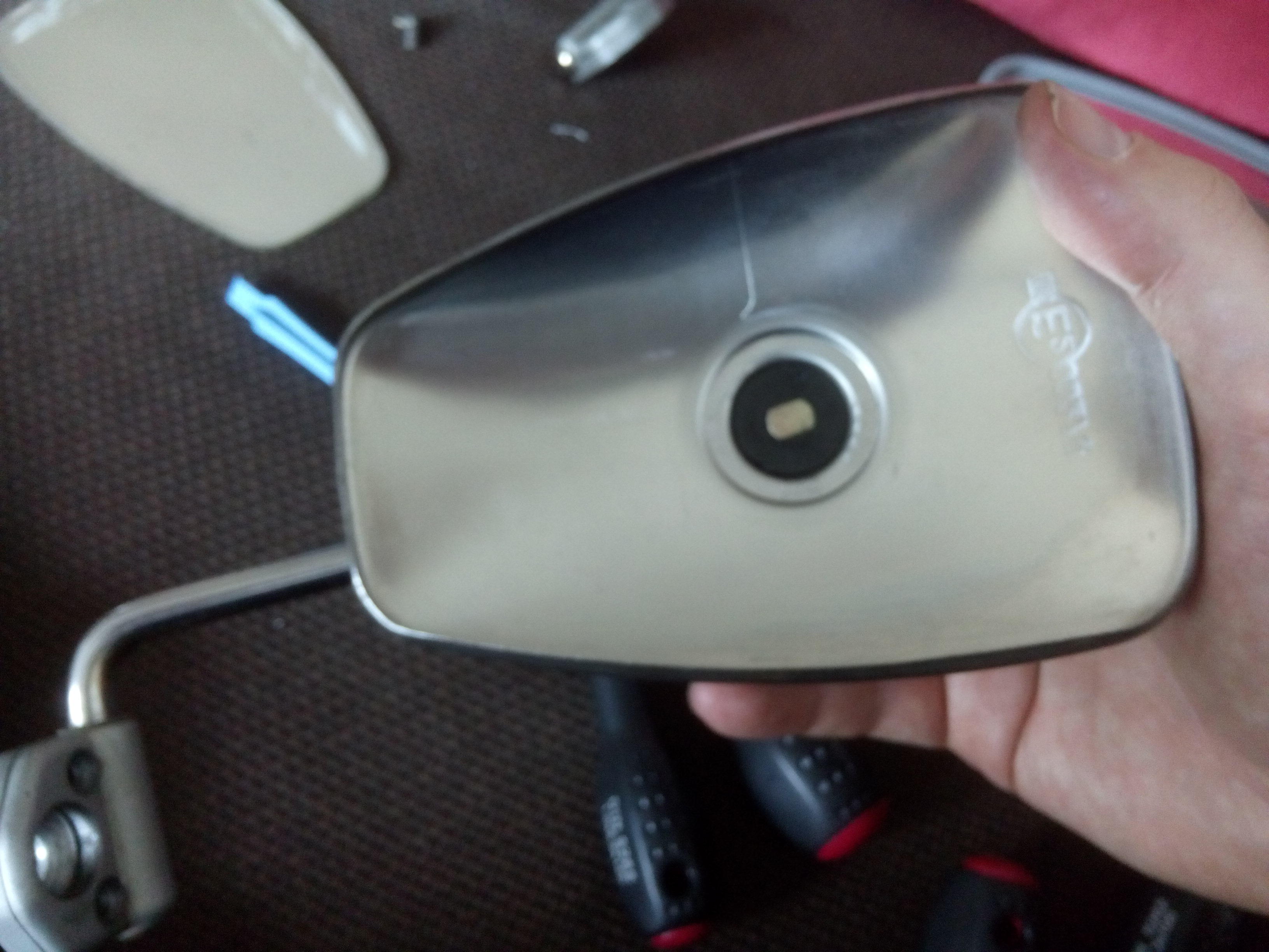
With the old beading cut away and the mirror removed it exposed the interior of the wing mirror assembly. There was a bit of dirt in here so I cleaned it out with electrical connection cleaner and put a very light coating of 3-in-1 over the central mounting point – not enough to impair the friction fit.
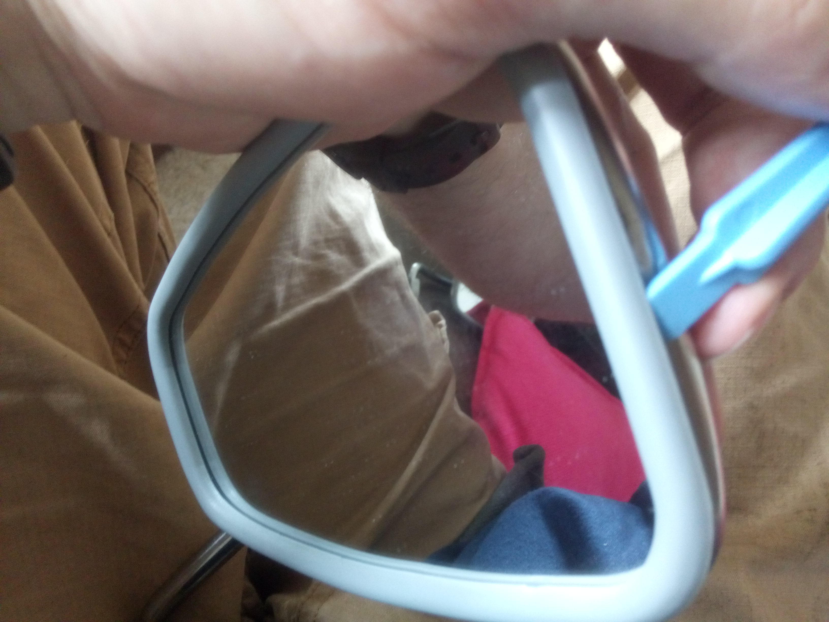
Fitting the beading wasn’t quite as simple as a push fit. Via a process of trial and error I found that the best way was to insert the narrow end fully into the lip and then use the light blue plastic tool provided to encourage the beading under the lip.
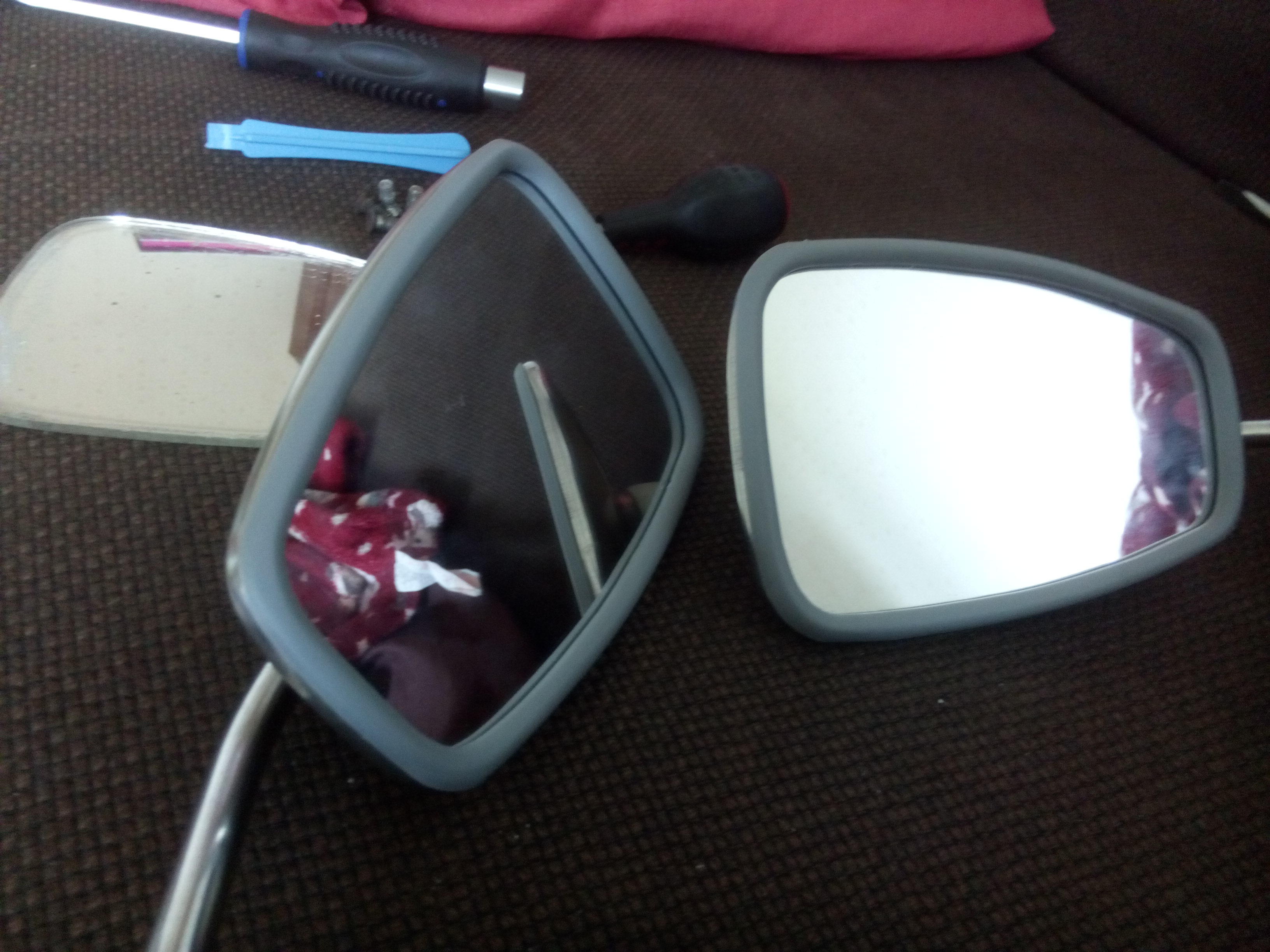
This ended up taking quite a bit more time that I expected but the results were worth it, two new mirrors that weren’t about to fall out.
See also: Replacing the wing mirror mounting bolts
SPREAD ANARCHY
don’t tell me what to do

DELIRANT ISTI ROMANI

Replacing and gaping the points on a 2CV
5th September 2015 12:06The ignition on a 2CV uses a wasted spark system – that is the spark plug fires on both ignition and exhaust strokes, the latter being wasted. This means that there is no distributor, it uses a low tension circuit breaker driven off the cam shaft to fire the spark.

As well as the circuit breaker the points also include a capacitor (know as the condenser) that resonates with the resistance in the coil to induce a high tension across the spark plug gap.
Over time the contact surfaces wear, as does the plastic cam follower, meaning the gap between the points at the fully open position reduces making the spark less efficient. Replacing the condenser and adjusting the gap is an item on the D (yearly) service list. If the contacts are excessively worn then they also need replacing and the gap setting.
First remove the fan and the rubber points protector – the latter is held on with 8mm bolts, I found a 1/4″ drive was best to get purchase on them given some of the tight clearances.
With these removed the points box is easy to access. If you are replacing any items then the box will need removing. Disconnect the spade connector at the lower right hand side and undo the 11mm bolts on either side and remove the box.
The box cover is held on with three screws, remove this first. Then remove the condenser which is held on by one screw to the left of the box and the contact screw that goes through the condenser connector, the spade connector, the insulator and secures into the spring blade mount. Carefully remove all these items and the lower (moving, positive) contact arm paying particular attention to how they fit together. The top (fixed and earth) contact arm is attached to the points box with a flat head screw that locks it into position, remove this and the top contact.
Re-fitting the new parts is the reverse of assembly:
Fit the top contact to the box leaving the screw lose. Hook the spring blade into the lower contact and place the mount into the insulator’s trough. With these three parts as a unit place them back into the points box.
Fit the condenser into its insulating mount and thread the contact screw through (in order, bottom to top):
- Condenser connector
- Spade connector (pointing up)
- Condenser’s insulating mount
- Points box
- Insulator trough
- Spring blade mount
Replace the earth screw attaching the condenser to the points box and, without replacing the cover, re-attach the points box to the car – the exact position isn’t vital as that will be determined when you re-time the ignition.
Using the 14mm fan retaining bolt screwed into the fan taper rotate the engine until the lower contact is fully open on the heel of the cam. Place a 0.4mm feeler gauge between the contacts and tighten the top contact retaining screw locking it into position ensuring there is a slight drag on the blade of the gauge. Rotate the engine again so the lower contact is open again on the other lobe of the cam and check the gap is still correct.
Replace the points box lid and seal, then re-time the ignition.