


Not the most enjoyable of jobs on a freezing cold day but still needs to be done.
Nothing to see here.
Not the most enjoyable of jobs on a freezing cold day but still needs to be done.
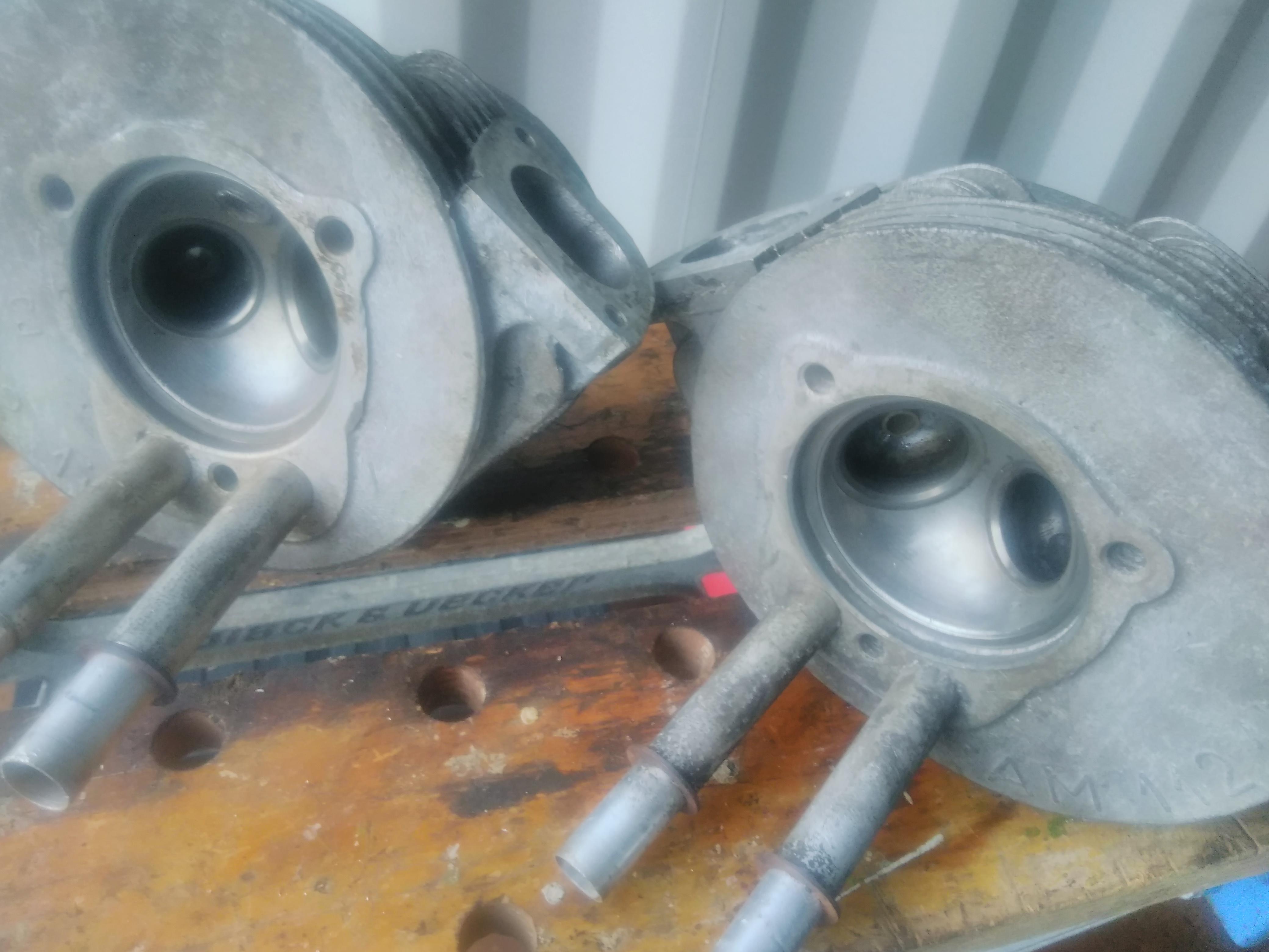
Nothing too aggressive but whilst I had the heads off I got the Dremel out and softened the hard edges in the inlet and exhaust ports.
These edges seem to be where the cast inlet meets the machined area in the valve bowls.. With a finger it was possible to feel the lip but with a small amount of grinding and polishing it now feels smooth to the touch.
Other than removing a few minor casting marks I didn’t do much as the ports were already reasonably smooth.
I doubt it’s actually going to improve matters measurably but this was the only opportunity I’m likely to have to do it, it didn’t take long, and I can now say it’s been done.
Wonder how many people looking for change after the earth passes an arbitrary point on its orbit of the sun also think astrology is bollox?
— Colonel Sponsz (@colonel_sponsz) January 1, 2017

Visited the Museum of the air battle over the Ore Mountains fought over that area in September 1944 when 60 Luftwaffe fighters (Me 109s and Fw 190s) intercepted a formation of 36 USAF B-17s shortly before they rendezvoused with their P-51 Mustang fighter escort.
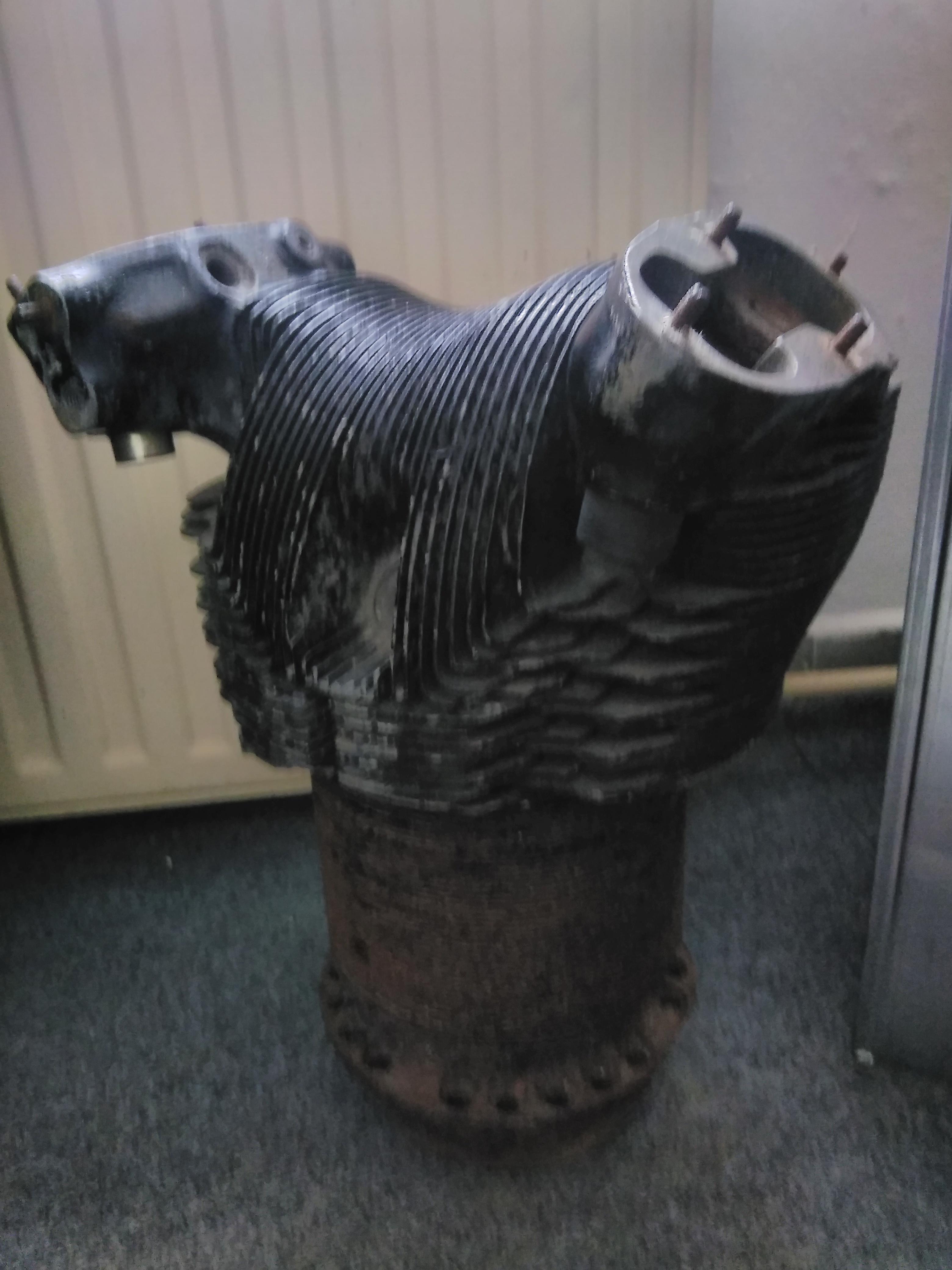
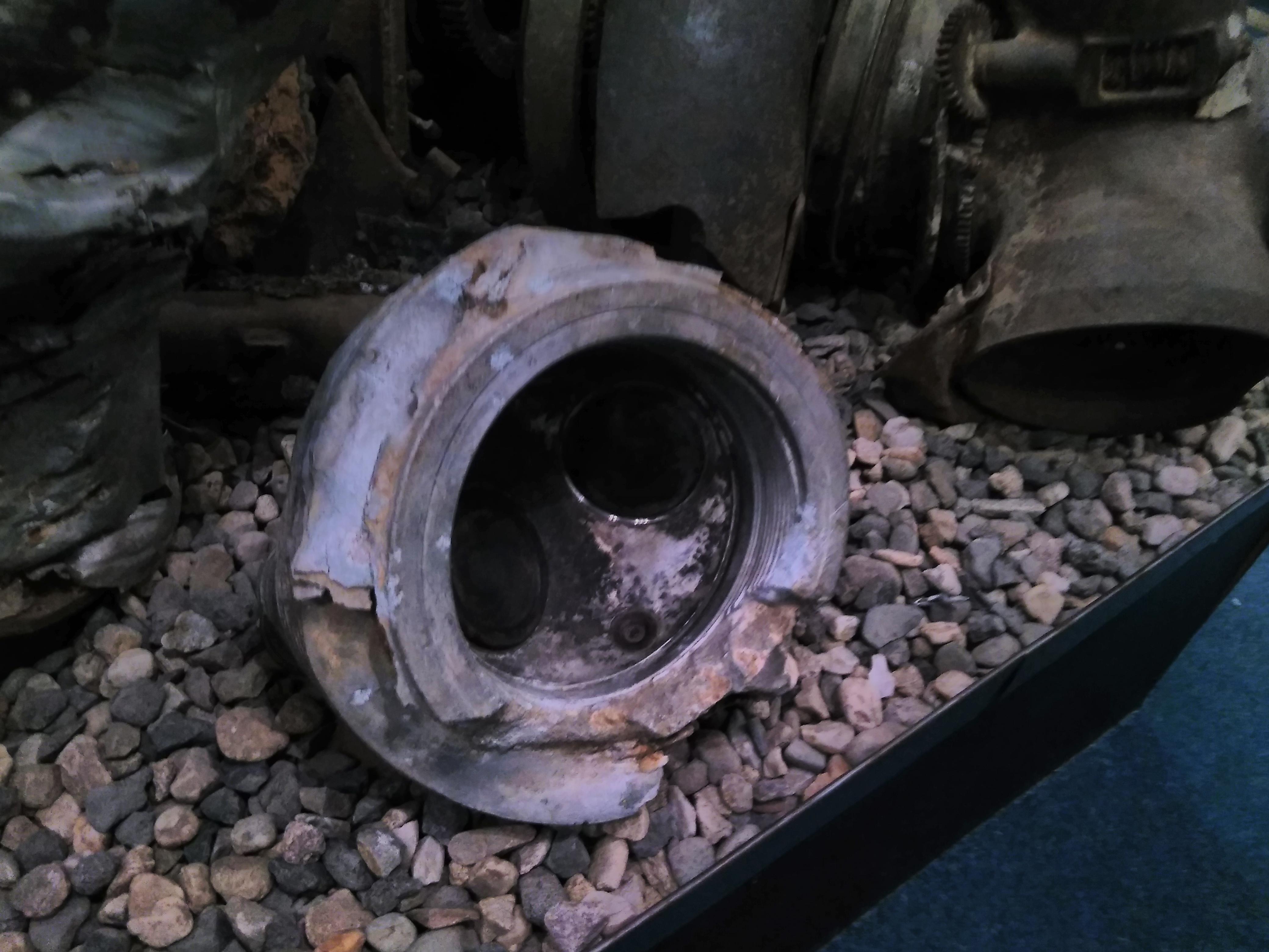
They had the wreckage of a BMW 801D engine from a Fw 190A-8/R2 Sturmbock of II.(Sturm)/Jagdgeschwader 4. As this is an air/oil cooled engine of the same vintage as the 2CV the similarities are striking.
Whilst the size is significantly different (2.9l per cylinder as opposed to 0.3l) the cylinder and head assemblies are very similar with a ferrous cylinder and finned aluminium head:

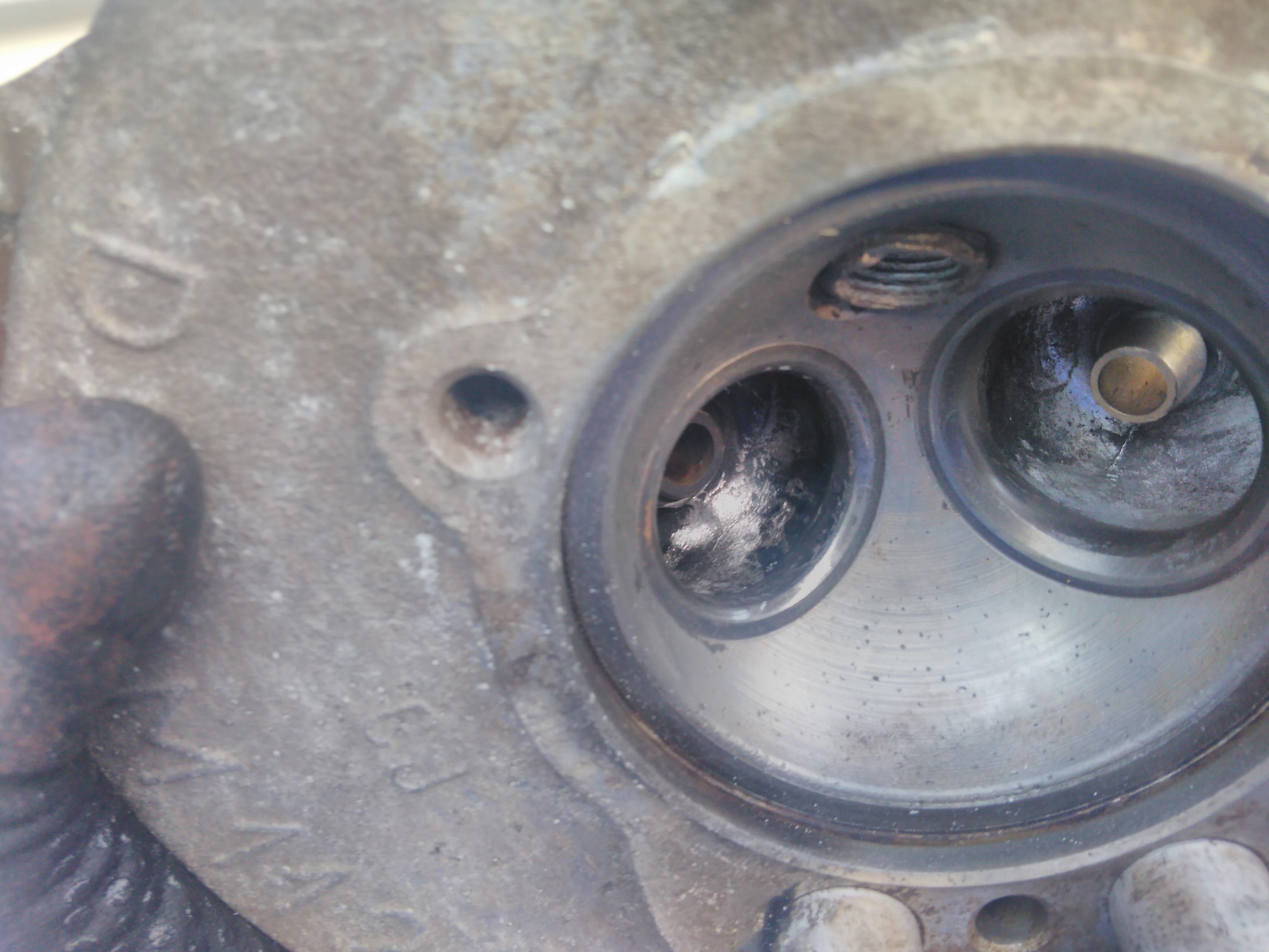
Likewise, inside the head, the domed combustion chambers are very similar with one intake and one exhaust valve, hardened valve seats and the spark plug situated in the same place.
Known as Black Monday, on 11th September 1944 the USAF launched a large number of bombing raids into the Reich. The Luftwaffe put pretty much every available fighter into the air to intercept.
The FW190s involved in the action over the Ore mountains had extra armour and 30mm cannons. They attacked the B-17 boxes in a tight formation known as Sturmbock (battering ram) opening fire at under 200m. The Me 109s were there to mop up any B-17s that were forced out of formation (Herausschuss) and to deal with the Mustang fighter cover which, in this case, arrived after the Surmbock attack.
The Museum is typical of a volunteer only effort: there are a large number of items in very dense displays with very detailed and comprehensive notes.

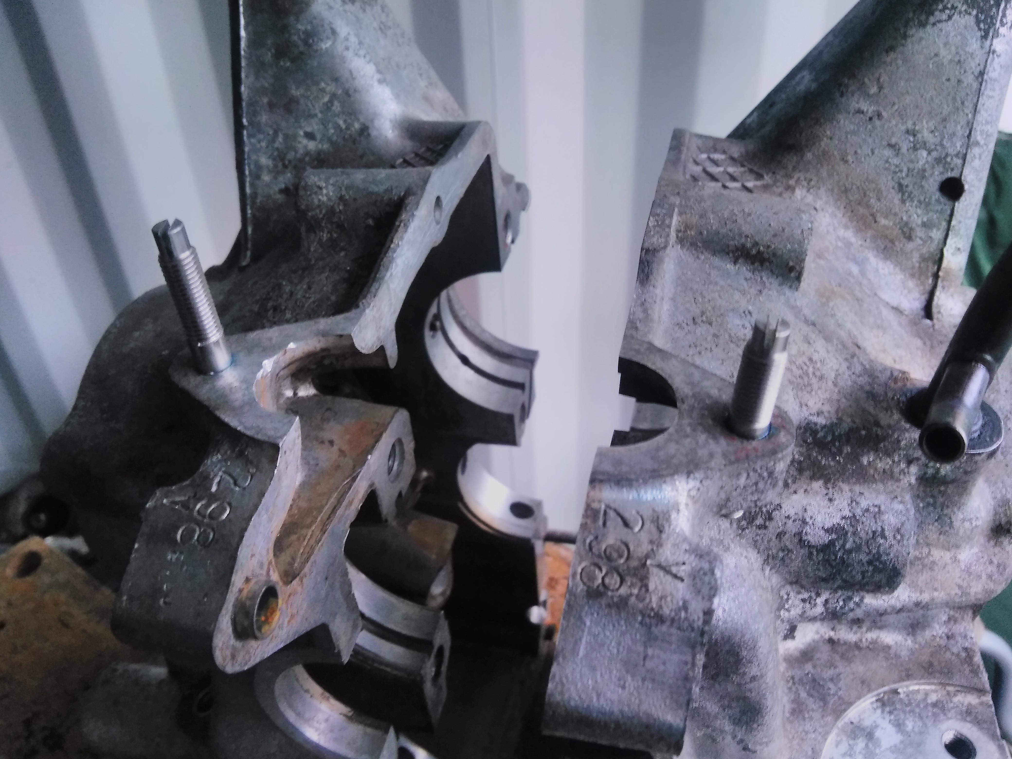
After removing everything from the crank case I cleaned it up with industrial strength degreaser and a pressure wash.
The dipstick guide had a bit of surface rust so that was cleaned up and painted with a couple of coats of black Hammerite.
The oil filler/ breather normally attaches with a pair of bolts but the V series engine had more practical studs. SPOG sell a pair of studs for the A series engine which are easily fitted (with a bit of thread lock for good measure).

The longer stud with the thicker band goes on the off side as there is an alternator mounting plate on that side in addition to the breather.
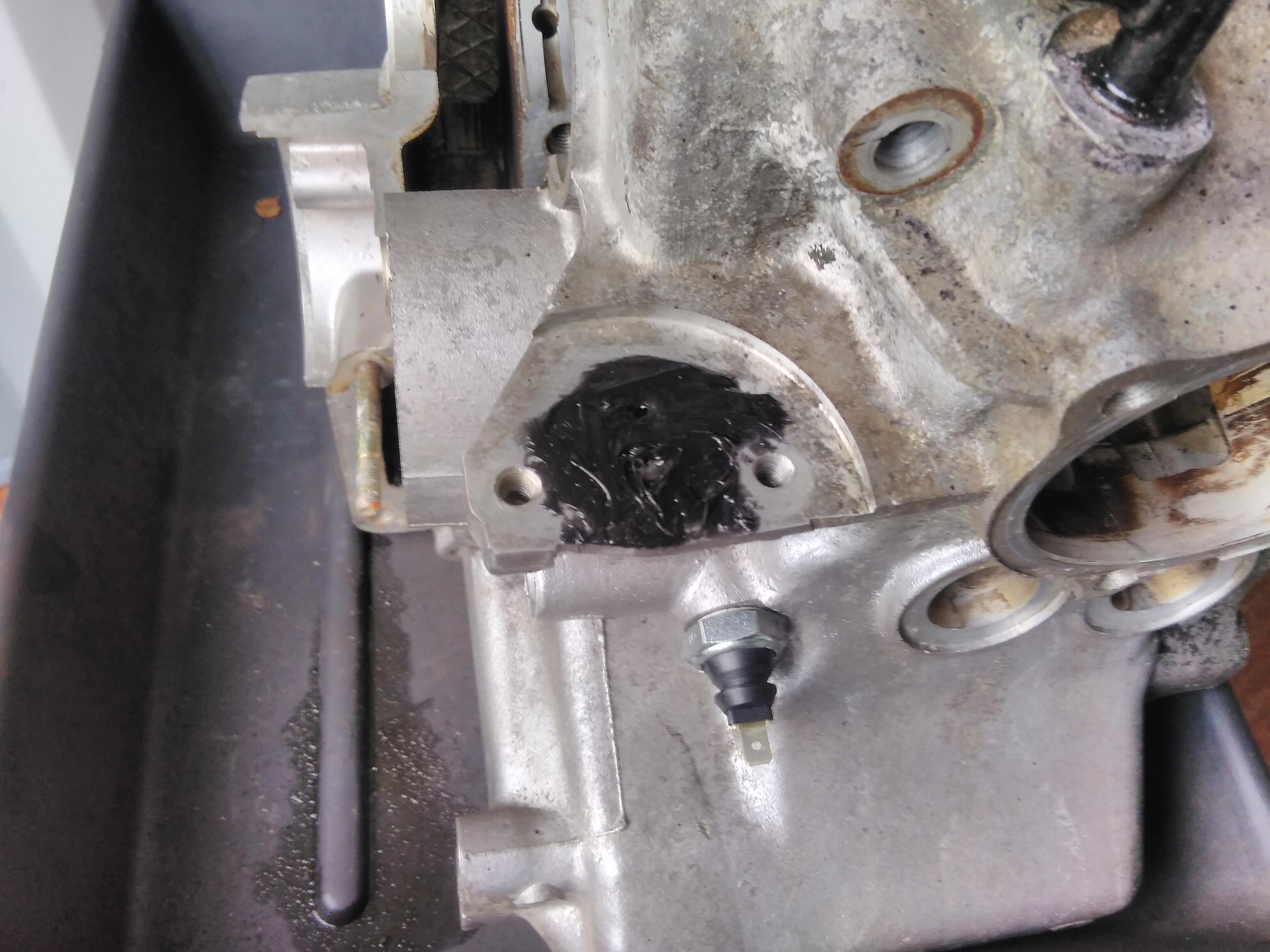
A new low oil pressure sender was fitted, complete with washer.
This one needed a 22mm spanner.

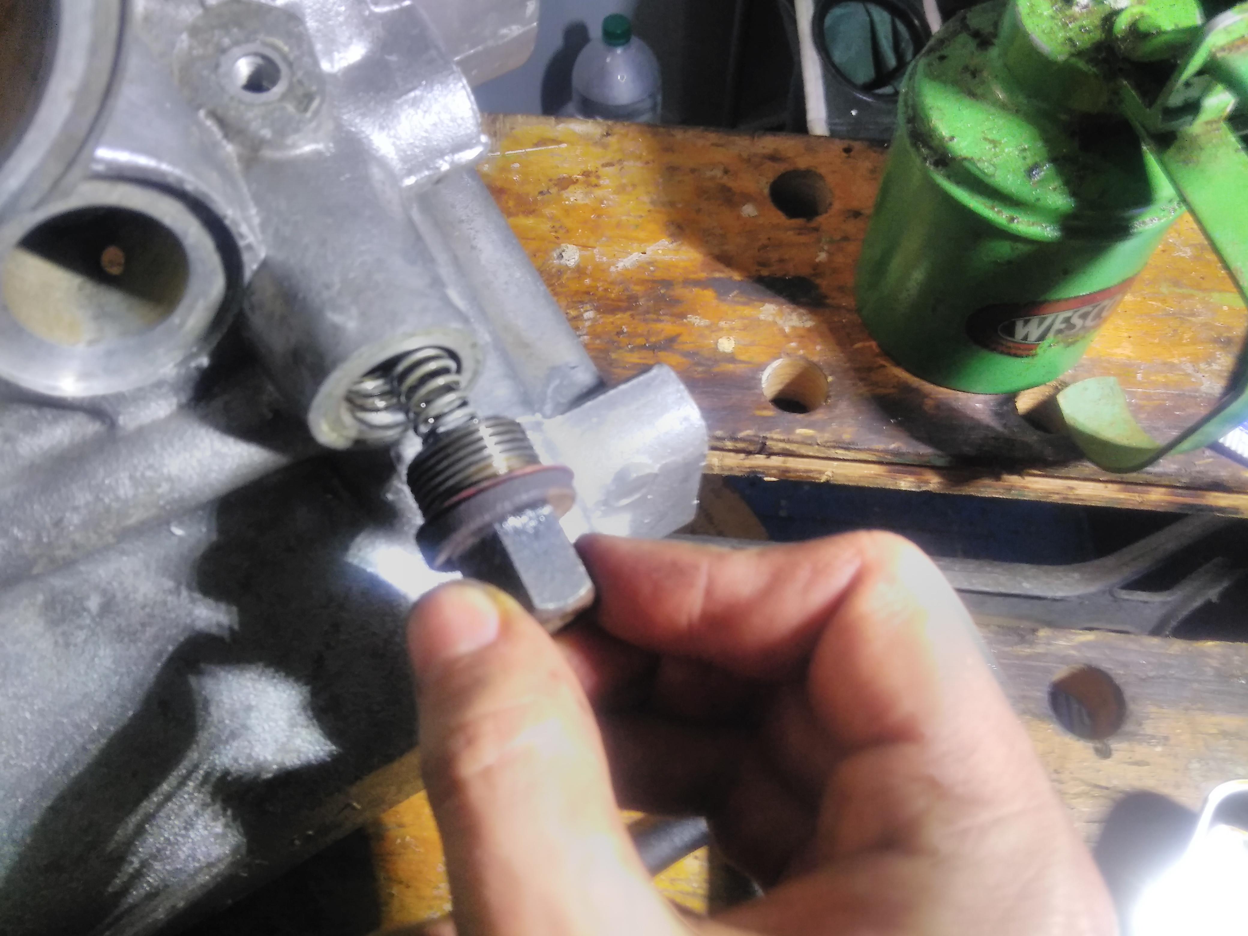
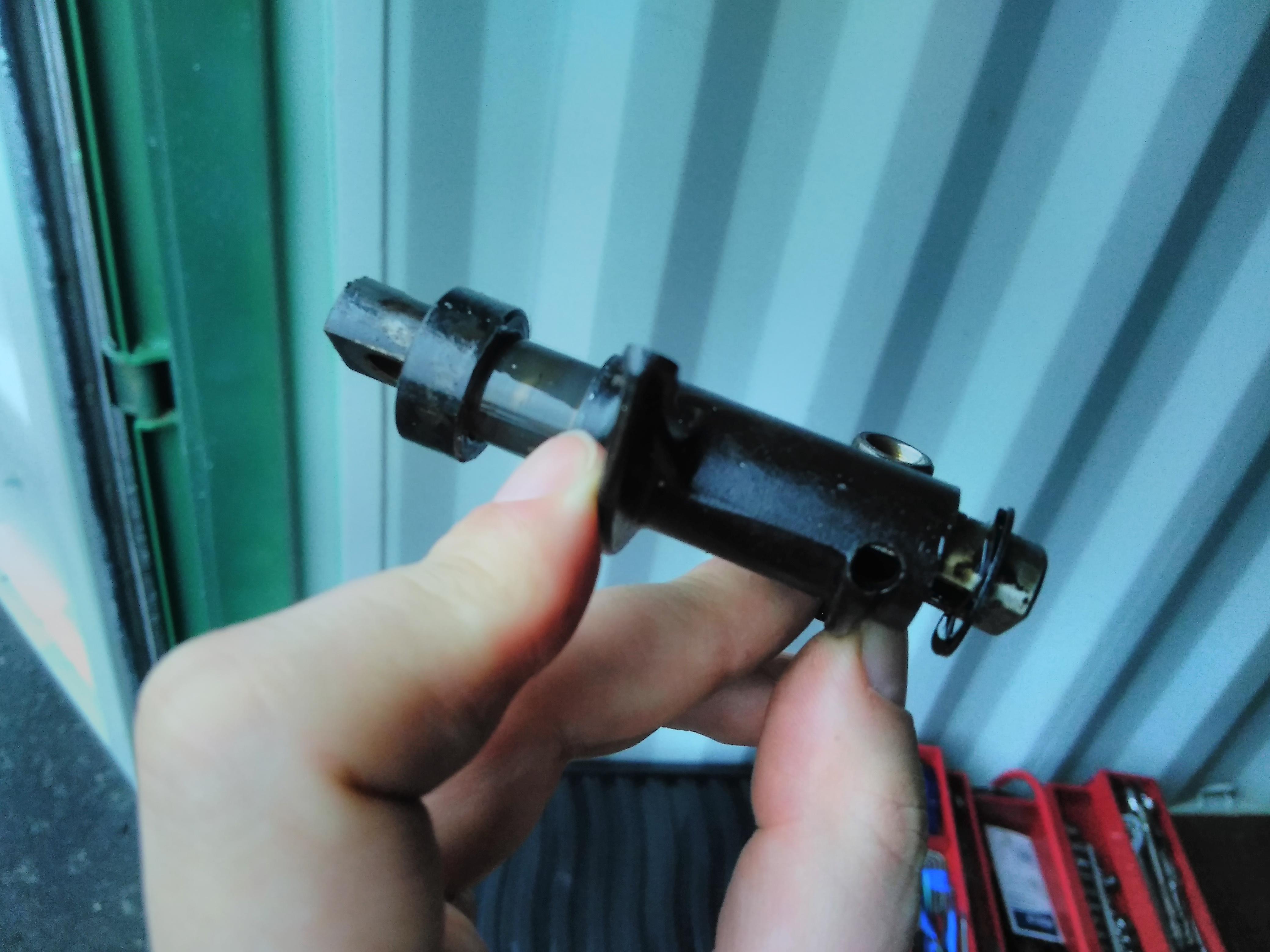
The oil pressure relief valve piston was liberally coated with fresh oil and inserted.
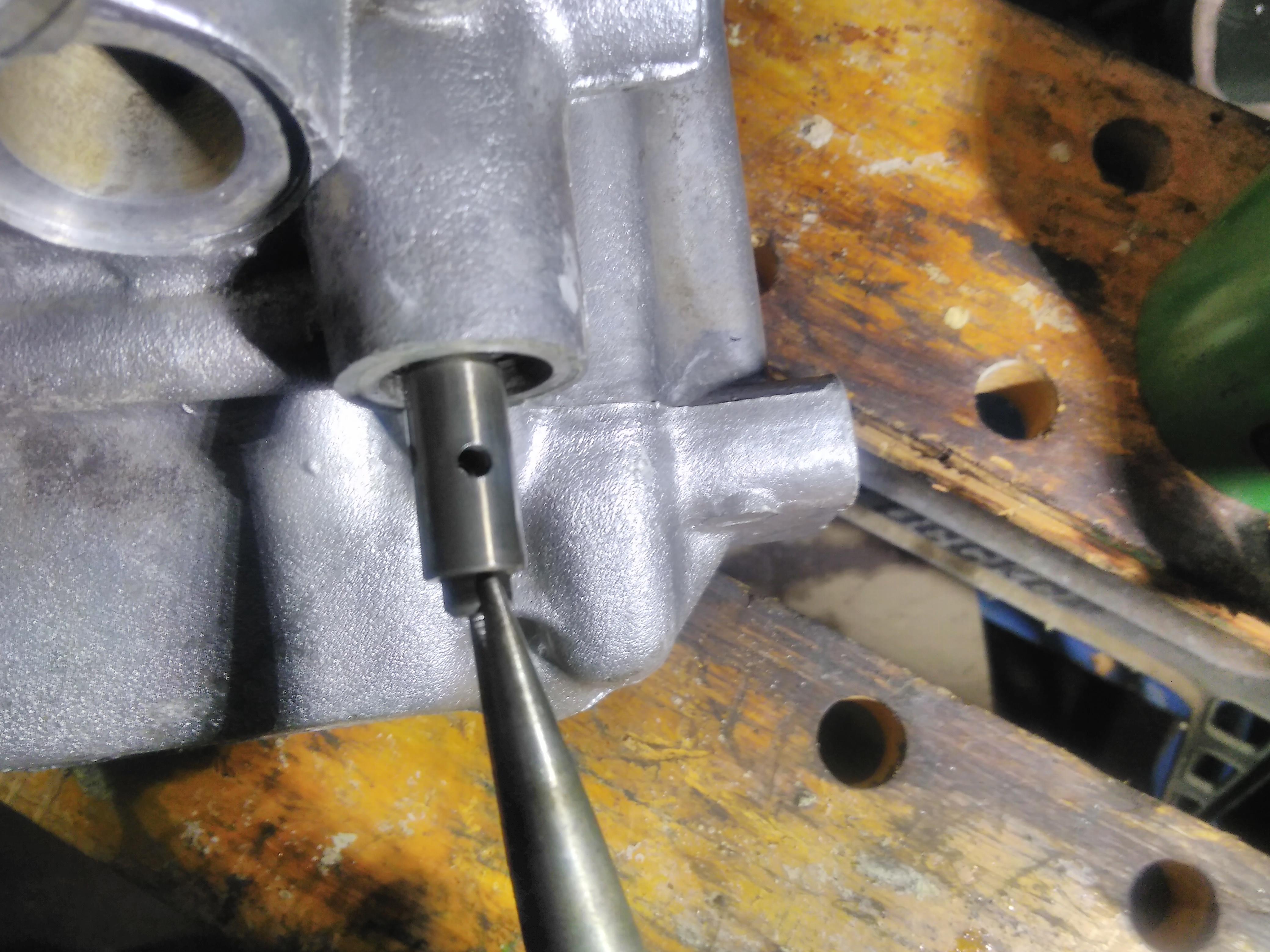
When fully home the only the nose stands proud of the housing.
The spring sits over the nose of the piston and, as I didn’t have a new copper washer, I annealed the old one by heating it until it was red hot and then letting it cool slowly.
The bolt is a 17mm and I don’t have a tightening torque for this so I went with a good strong tweak with the breaker bar which should be enough to crush the washer slightly.

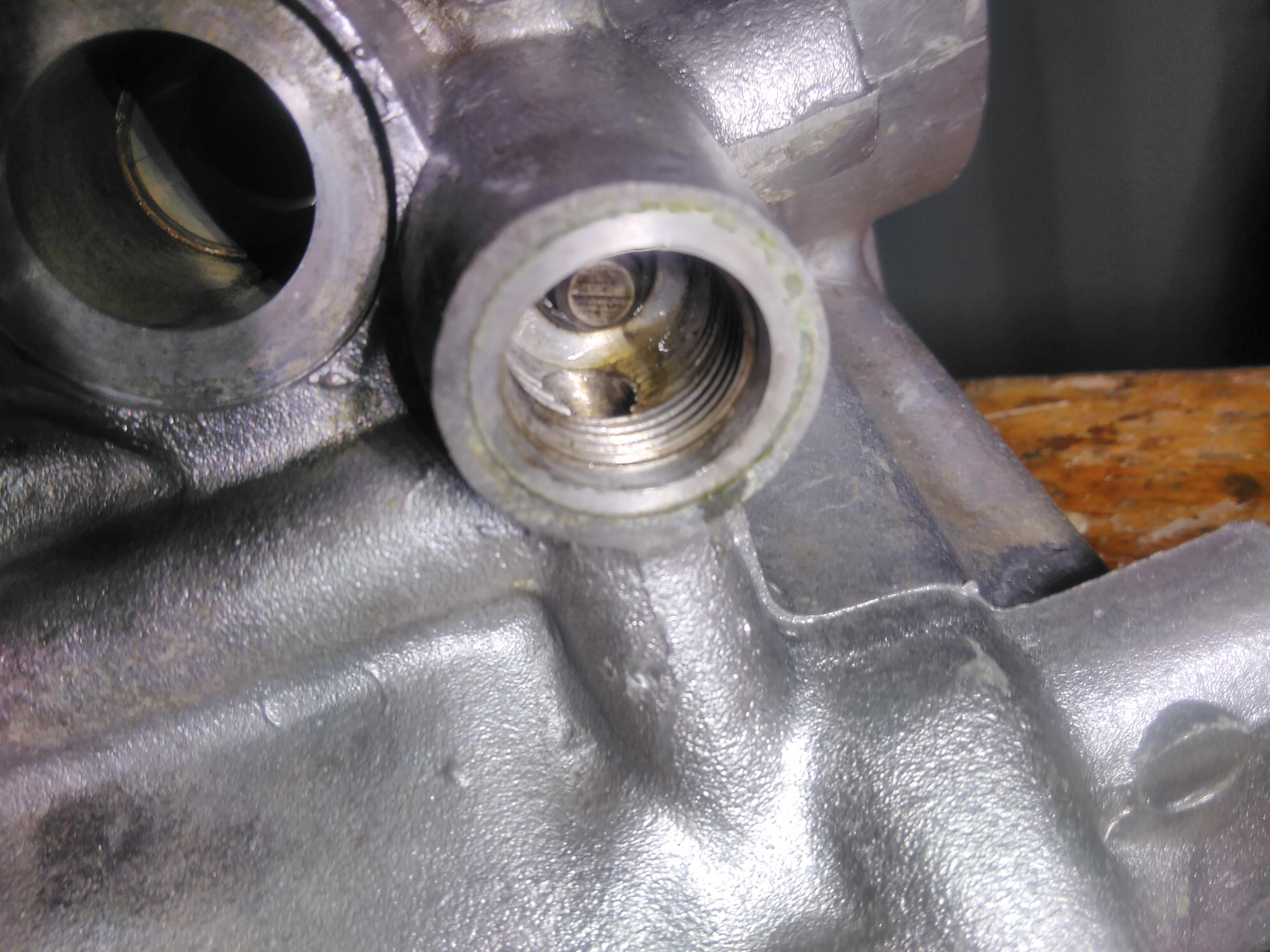
Another SPOG item is the 3/4″ thread oil filter spigot. A bit of thread lock and this was firmly screwed into the oil filter mounting plate.
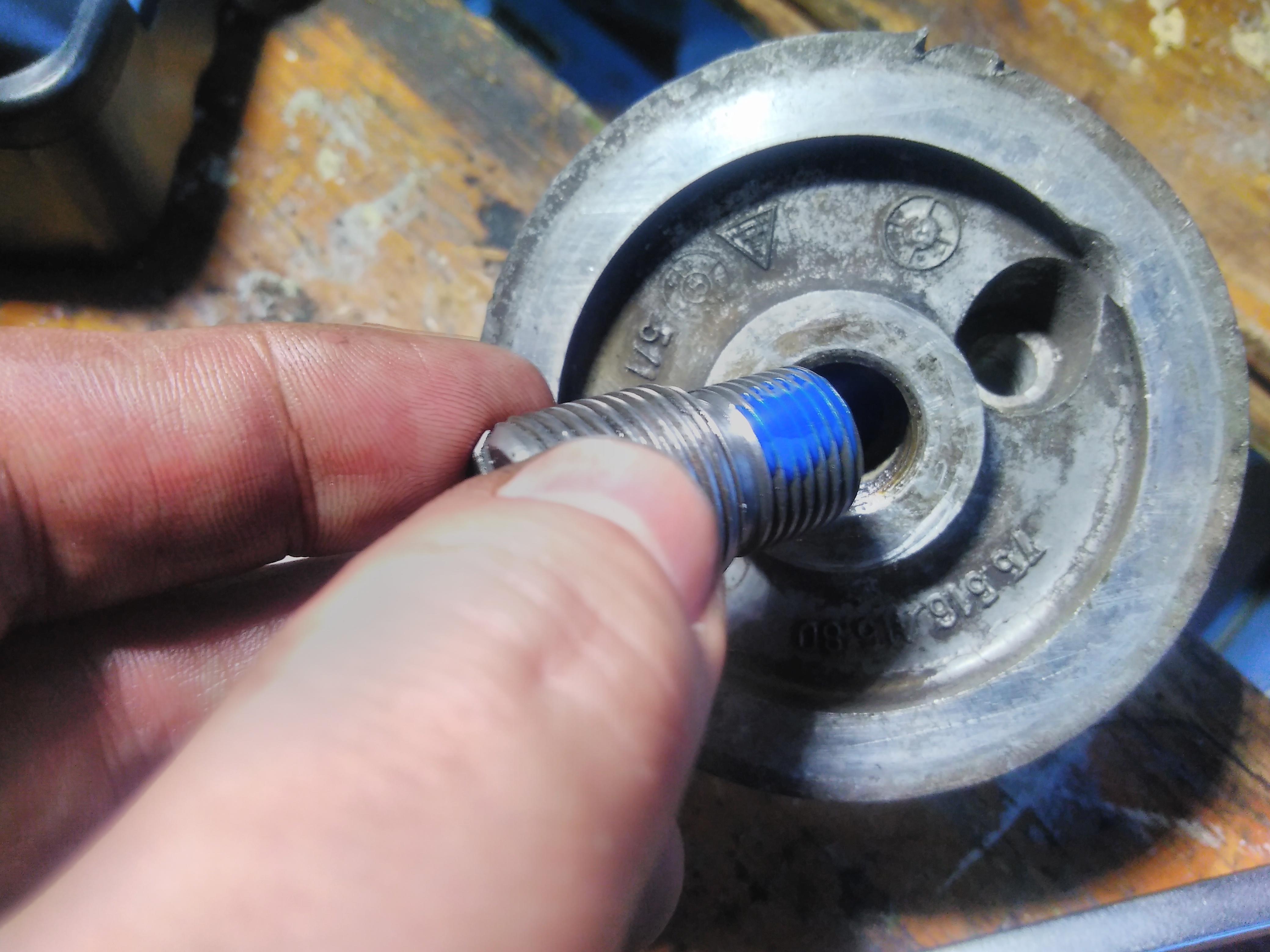
With a new o-ring and some sillyfoam sealant the mounting plate was re-attached to the crank case with the two alan bolts.

One of the advantages of the much more common 3/4″ thread is that a sandwich plate can be mounted. In this case I’ve got oil temperature and pressure senders – important information to have available for an air/oil cooled engine.

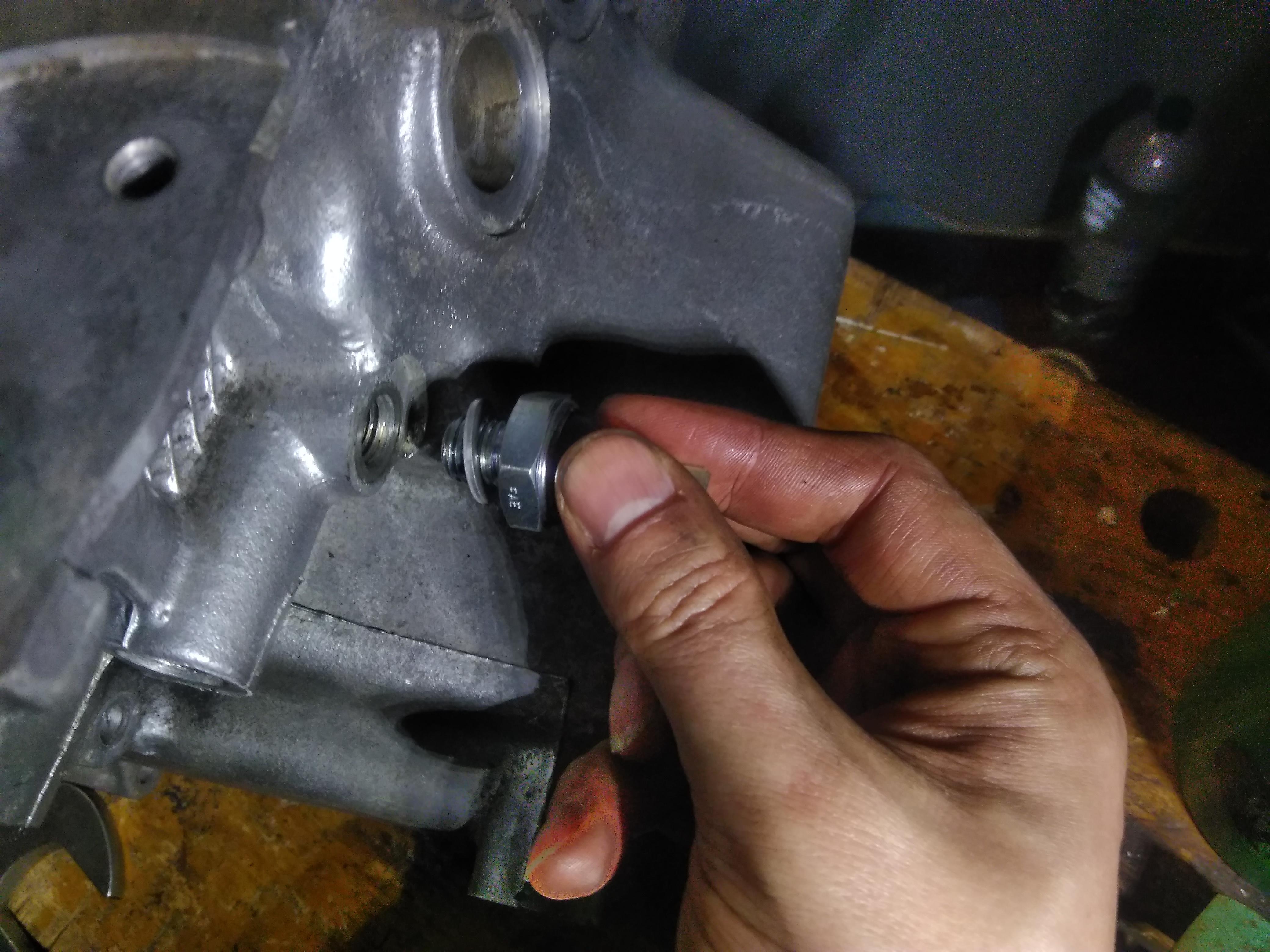
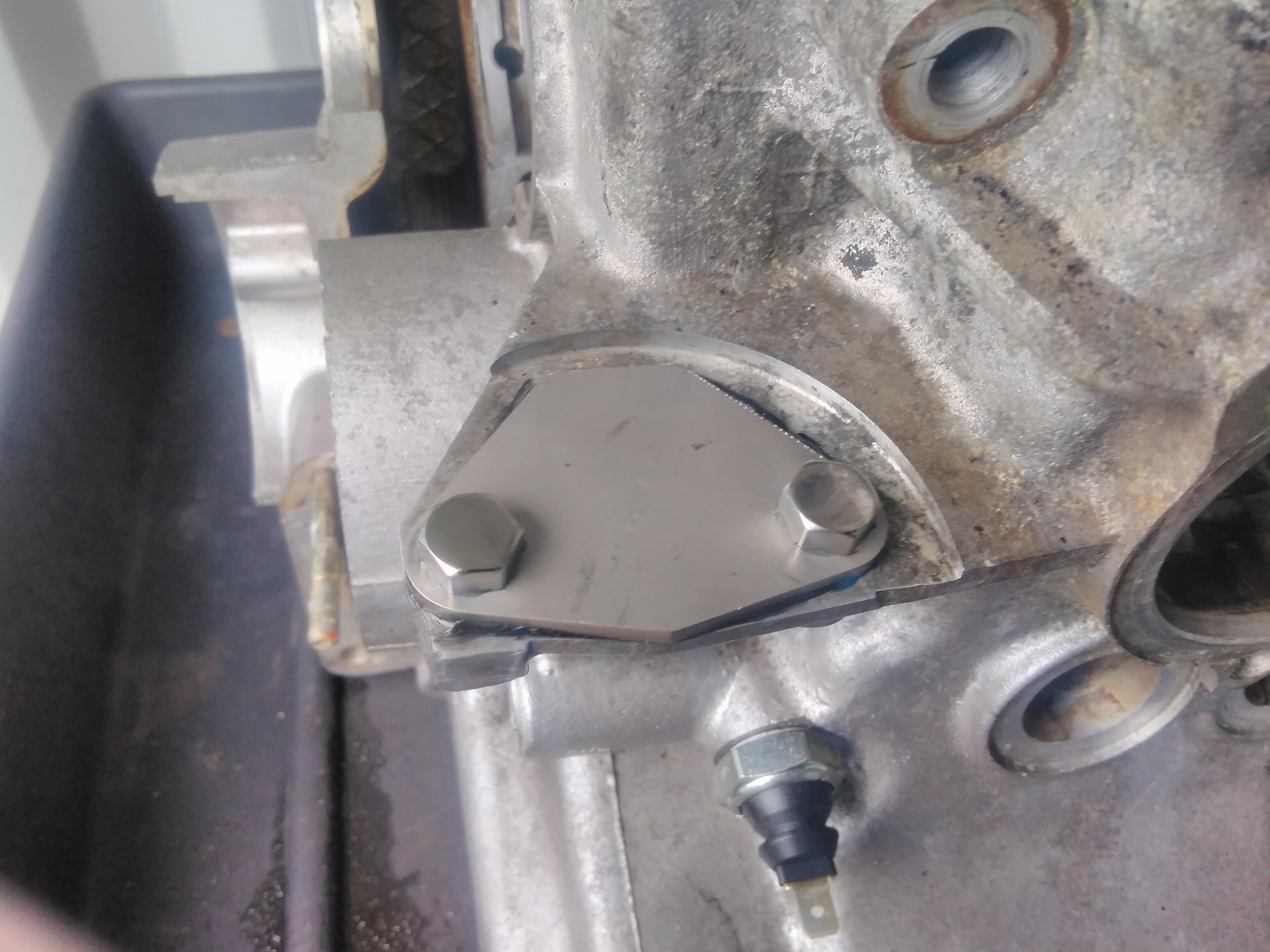
As I’m planning to fit an electric fuel pump I’ve got a stainless steel blanking plate for the standard, mechanical, fuel pump mounting point. This is important as, without the actuator rod, omitting the fuel pump would leave a hole in the crank case.
After applying a generous amount of high temperature sillyfoam sealant the blanking plate was secured with stainless steel M7 nuts.
In a model shop I saw a “Sauss Ente” 2CV kit.

Not only did it stand out to me because it’s a 2CV but also because I’d seen the same livery at Le Mans Classic.

The “Sauss Ente” (Speedy duck) was a German special edition – in the fine tradition of making 2CV special editions by the application of graphics to an otherwise mechanically standard car. Backing up the name, the graphics include the 0 to 60 time of 59.4 seconds. It also featured a Club interior, a monospoke steering wheel and an Ami 6 dashboard.
I’m not entirely sure what I’ve been reading tonight but I enjoyed it so the SAN loss must have been worth it.

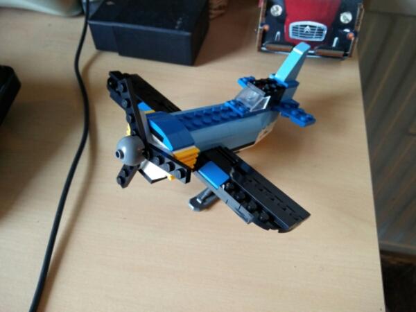
First pass at modifying the stock plane into a smaller Lego Gee Bee. Main changes were shortening the wings and fueslage, and a reprofiling of the tail.

There are two steps to removing the valves from a 2CV’s cylinder head, you need to remove the rocker arms before you get access to the valves.
The rocker arms sit on pivots that are held in at the top by the cylinder head nuts and at the bottom by a bolt with a special head with two flats. Fortunately an adjustable spanner provided enough purchase to free them off without needing to resort to “advanced” techniques.

With the bolts removed the rocker arms come free.

The rocker arms slide freely on the pivots and there are two sets of washers on them, a thick one one at the top and a spring washer and a thin washer at the bottom.
Now to remove the valves themselves. (Not too many pictures of this as it’s a job that requires three hands at the best of times…)
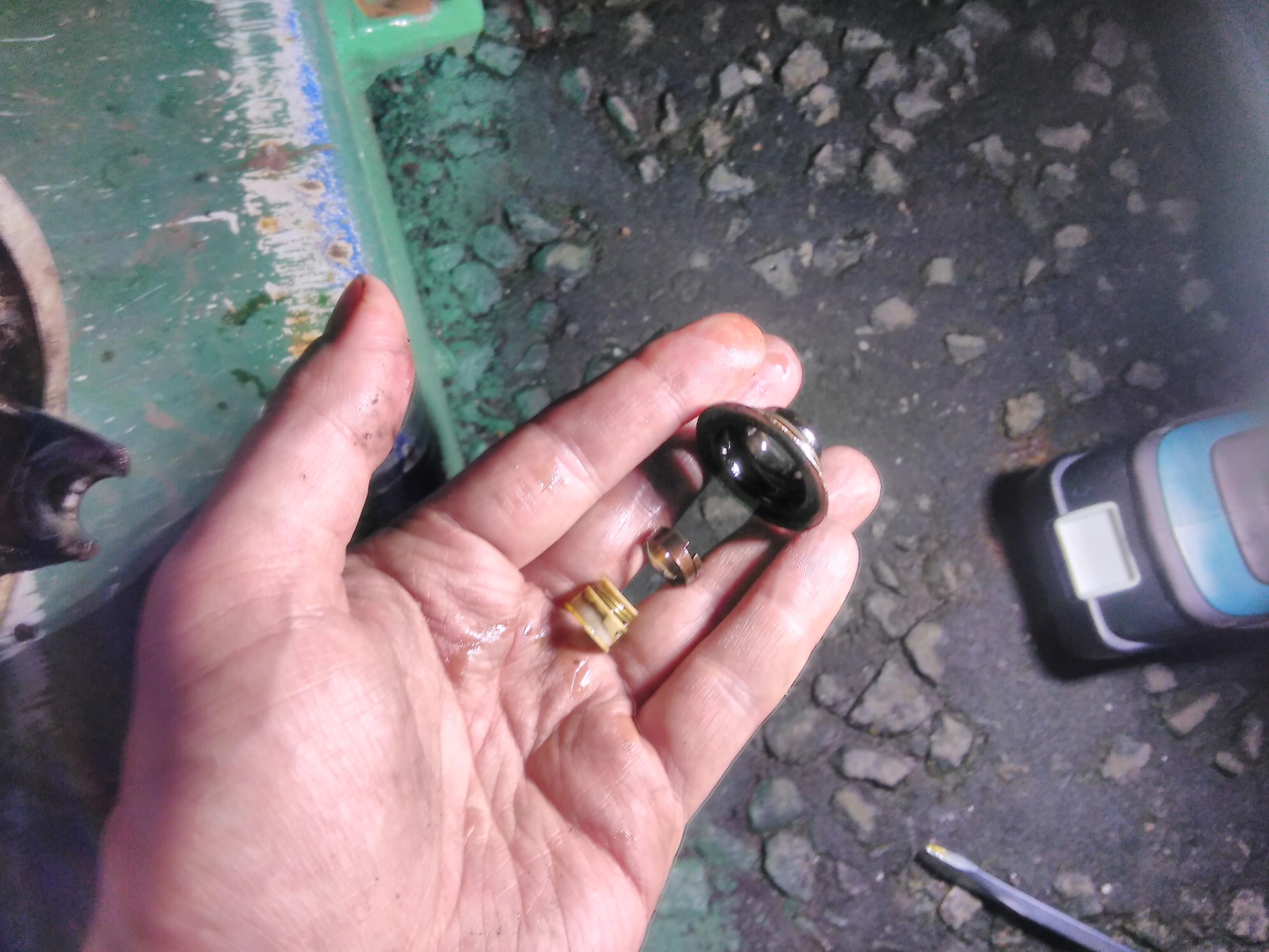
First a digression about how the valves are held in place. At the top of the valve stem there are a set of circumferential grooves which match the ridges on the inside of the semi-circular collets. The outside surface of the collets has a slight taper that seats them in the valve spring retainer plate that sits on top of the spring.
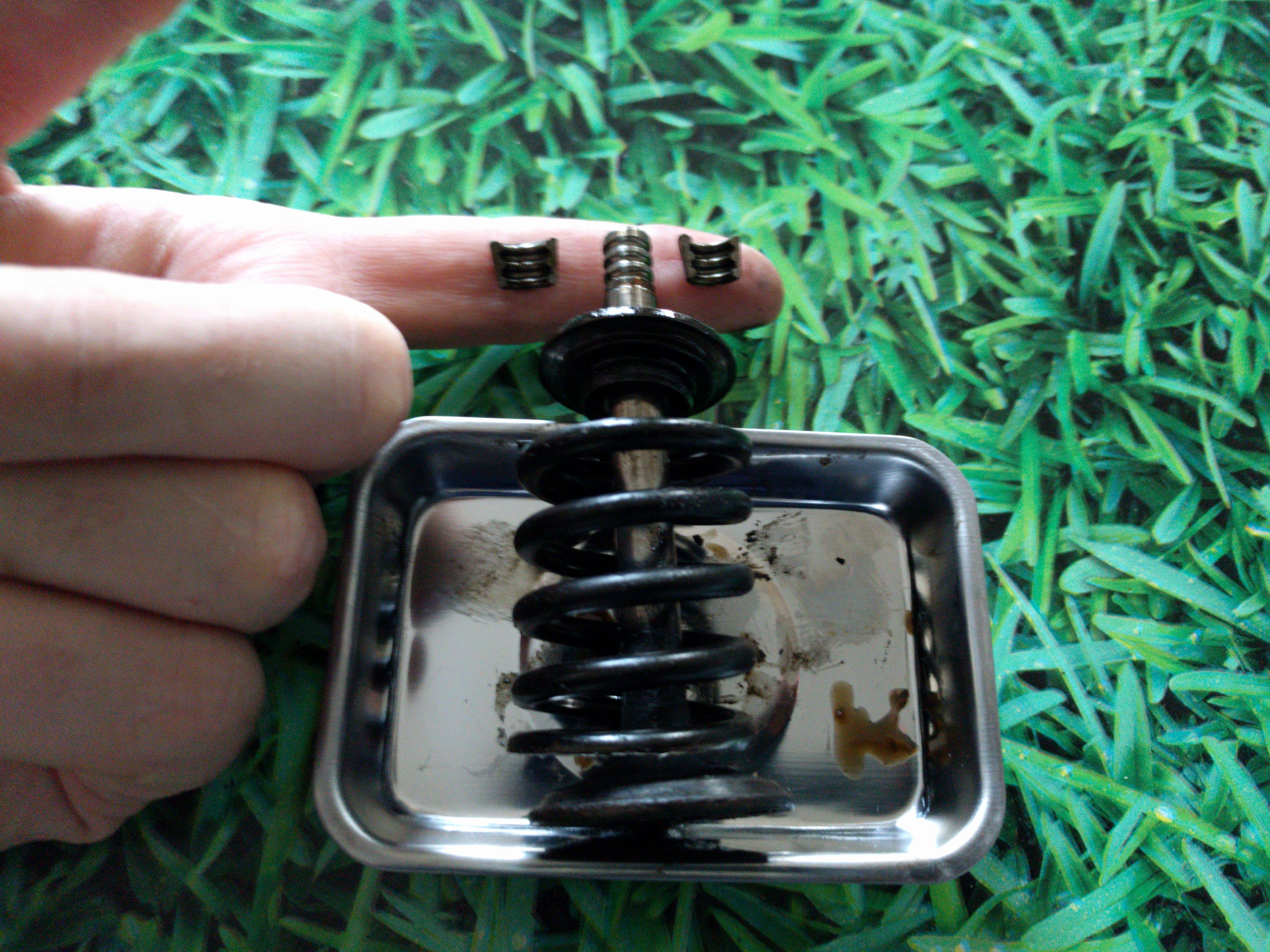
As that taper is constantly under pressure from the spring and will be expanding and contracting as the engine heats up and cools down it’s going to stick so, before compressing the spring, give it a small percussive persuasion to free it.
With a valve spring compressor (effectively a large C clamp) in place and the percussive persuasion having been applied it’s time to wind in the threads. When the collets are clear of the compressor collar you can go in with a magnet and extract them.

After fully unwinding the compressor to remove the tension, the valve springs lift off.

The valves then push though into the combustion chamber and can be removed.
Finally the valve stem oil seals can be removed. With the valve spring seats removed the metal collar can be prised off which allows the seal to be pulled off the valve stem.
