


Nothing to see here.

EDEN Mehari Electric Car
We are just a few years away from the 50th anniversary of the Méhari, and the 2CV Méhari Club Cassis got to thinking of a concept car to glorify this model symbolises the leisure car of excellence.
This model had to respect the tradition of the Méhari and be recognisable at first glance, and therefore there was no question of changing the form. You will notice in the concept car, the only exception to change is for security, because we have installed a rear roll bar and 3-point seat belts.
We wanted this vehicle to be elegant, the French elegance. This can be seen in the detail and quality of the upholstery entirely made in are workshop at Carnoux, and in the paintwork realised at our workshop at Cassis.
The third point is the modernity, because we want the Méhari to continue into the future. The Méhari will soon be 50 years old, for us 50 years old is the age of reason. We implanted an electric heart because pollution and consumption are subjects that concern the consumers and our society in general. We wanted to increase the longevity of the Méhari.
There is still a great demand for the Méhari. A problem which limits us in the construction of the Méhari, is that to build a Méhari we need a base to build from, this means finding a wreck with registration papers and building around that. This is no longer the case. The Méhari Club has become a car constructor. We will now be able to create our own chassis numbers and issue our own registration papers.
When we started this adventure we entered into contact with our clients and Méhari enthusiasts, and they encouraged us to think about commercialising this type of vehicle. The vehicle has recently passed shock and electromagnetic tests and it could be commercialised. Of course we will need to do some optimising and on road tests to ensure as always the high standards of quality and security that our clients have come to expect of our products.
To respect the tradition of the Méhari we decided to keep the original gearbox and a maximum of other parts made by us using the original Citroën moulds and tools. Of course there are some parts made specifically for the electrical motorisation. We kept the gearbox so that Méhari enthusiasts would have that gear lever and find the same unique sensation of driving a Méhari. Also the ability to change gear helps the vehicle to advance more efficiently on a slope.
We decided to use tried and tested technology. The batteries are Lithium iron phosphate. We chose a technical solution that provides a good balance between performance, reliability and longevity of batteries. We have two difference battery packs. The standard battery pack which provides a range of around 80Km (50 miles), and we have an extended pack with a range of 120Km (75 miles). This of course depends on the style and manner in which the car is driven. Given that most users do not drive more than 50Km (30 miles) a day we are sure the range is secondary for this type of vehicle. It is about the pleasure of driving wind in the hair and in almost complete silence.
We have a short charge time of 30Km (20 miles) per hour. In less than 3 hours the batteries are fully charged.
With the Eden we consider we have the project that bears the closest resemblance in look and feel of the original Méhari.
An advantage for us which is an element essential for our clients, is the experience and expertise of our upholstery and mechanical workshops. They have used the maximum of original Méhari parts to create this unique model.

Assembly is – of course – the reverse of removal.
Note: as there isn’t any oil circulation until the engine is running, lots and lots of oil is applied everywhere during re-assembly so that there won’t be un-lubricated metal-on-metal when it starts running. Additional lubrication with petroleum jelly was applied to some virgin metal surfaces which need more lubrication, this has a higher viscosity so will adhere for a bit longer during first start-up.
Starting with the off side crank case shell (the one with the studs in it) the crank and cam shafts go in. There are locating lugs in the bearing receivers and it’s important to line up the corresponding hole in the bearing shells when placing them. If you don’t the crankcase won’t shut properly.
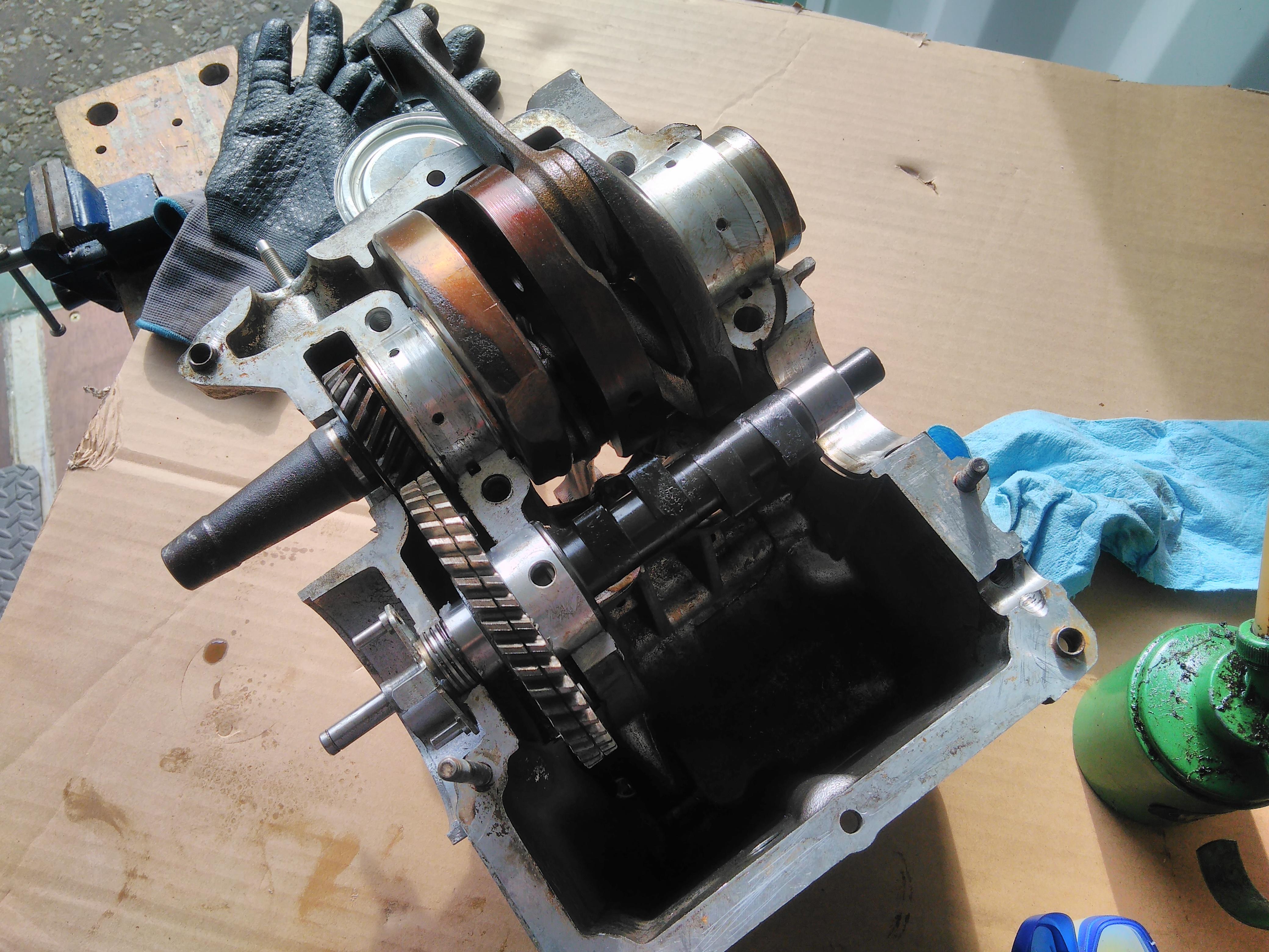
The timing marks on the crank and cam gears must be aligned.

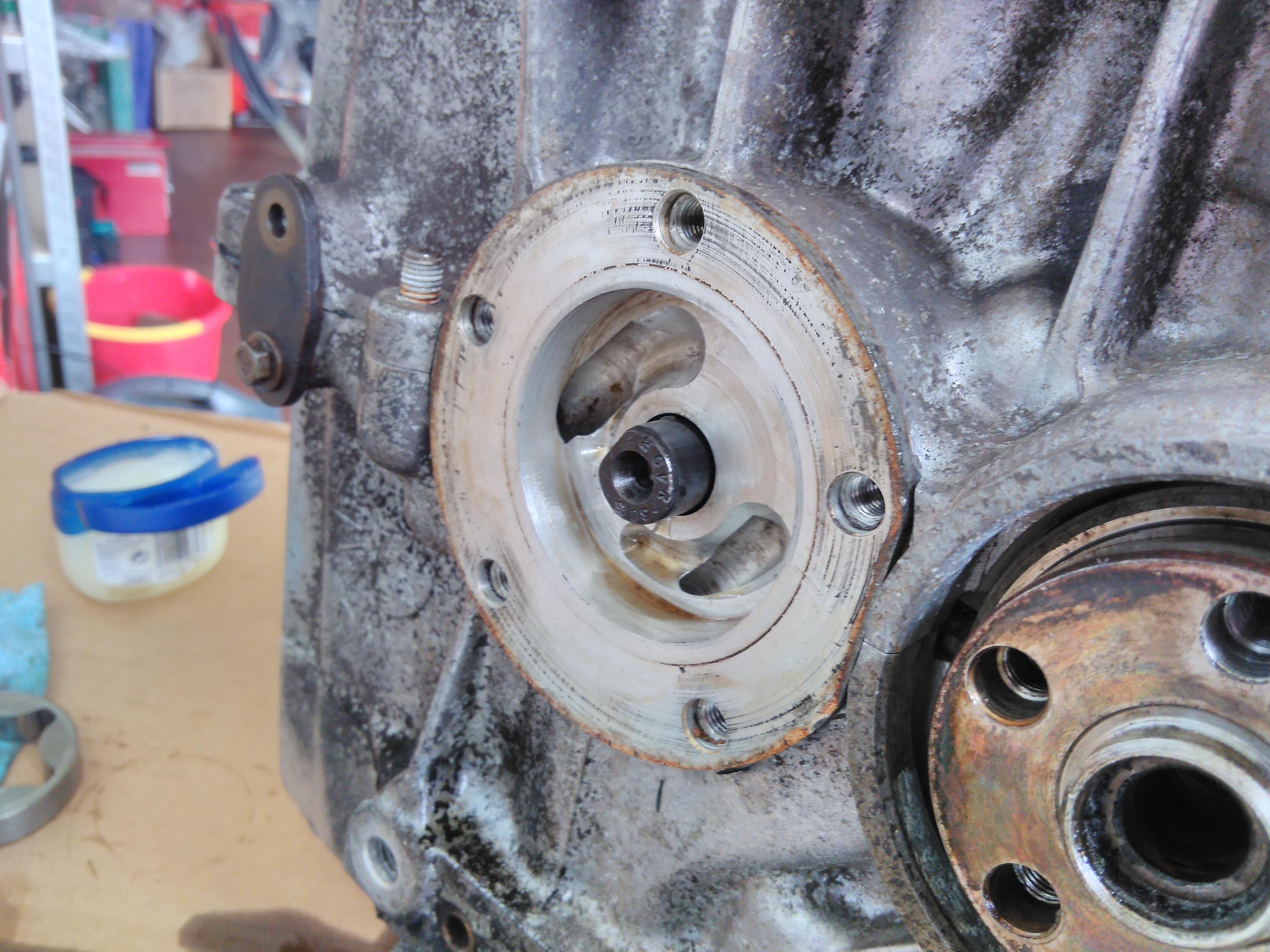
The oil pickup is fitted and the retaining bolt is secured.
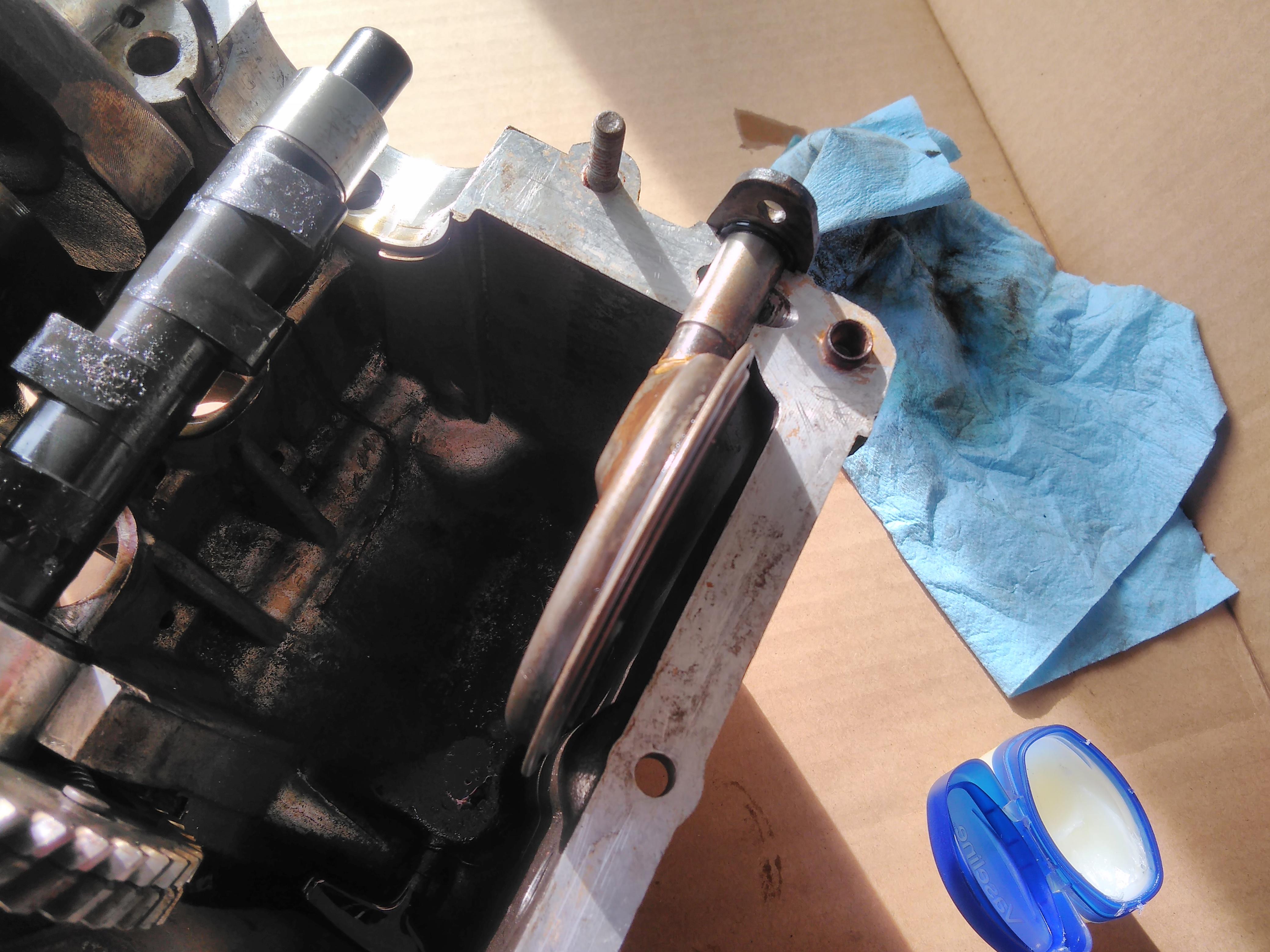
The crank case halves are now ready to be joined, a thin bead of high temperature sealant was run round the mating surfaces.
Final check as the crank case halves are closed, the timing marks are still aligned.
The four 16mm crank case bolts can be put in finger tight at this point.
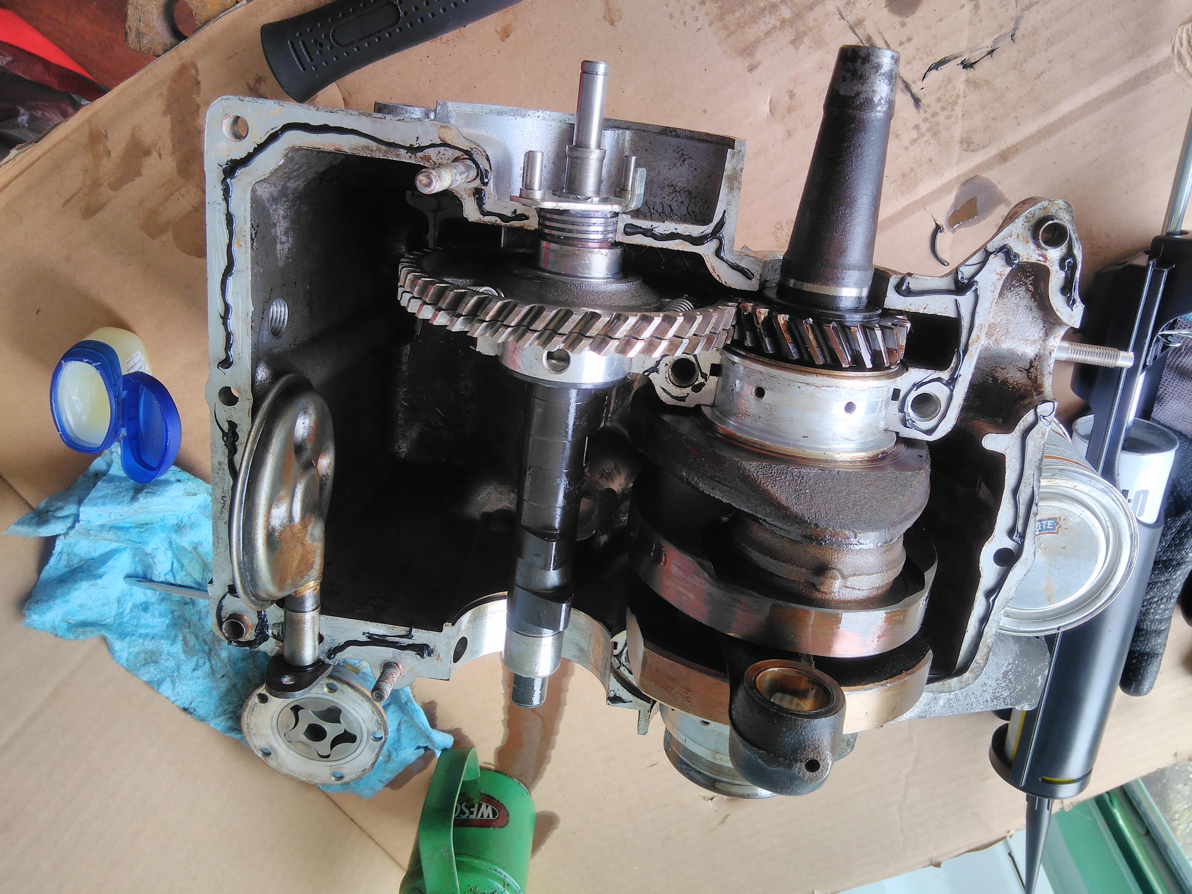
Next, the oil pump can be fitted to the end of the cam shaft. Start with a new paper gasket, this is dry fitted with no sealant.
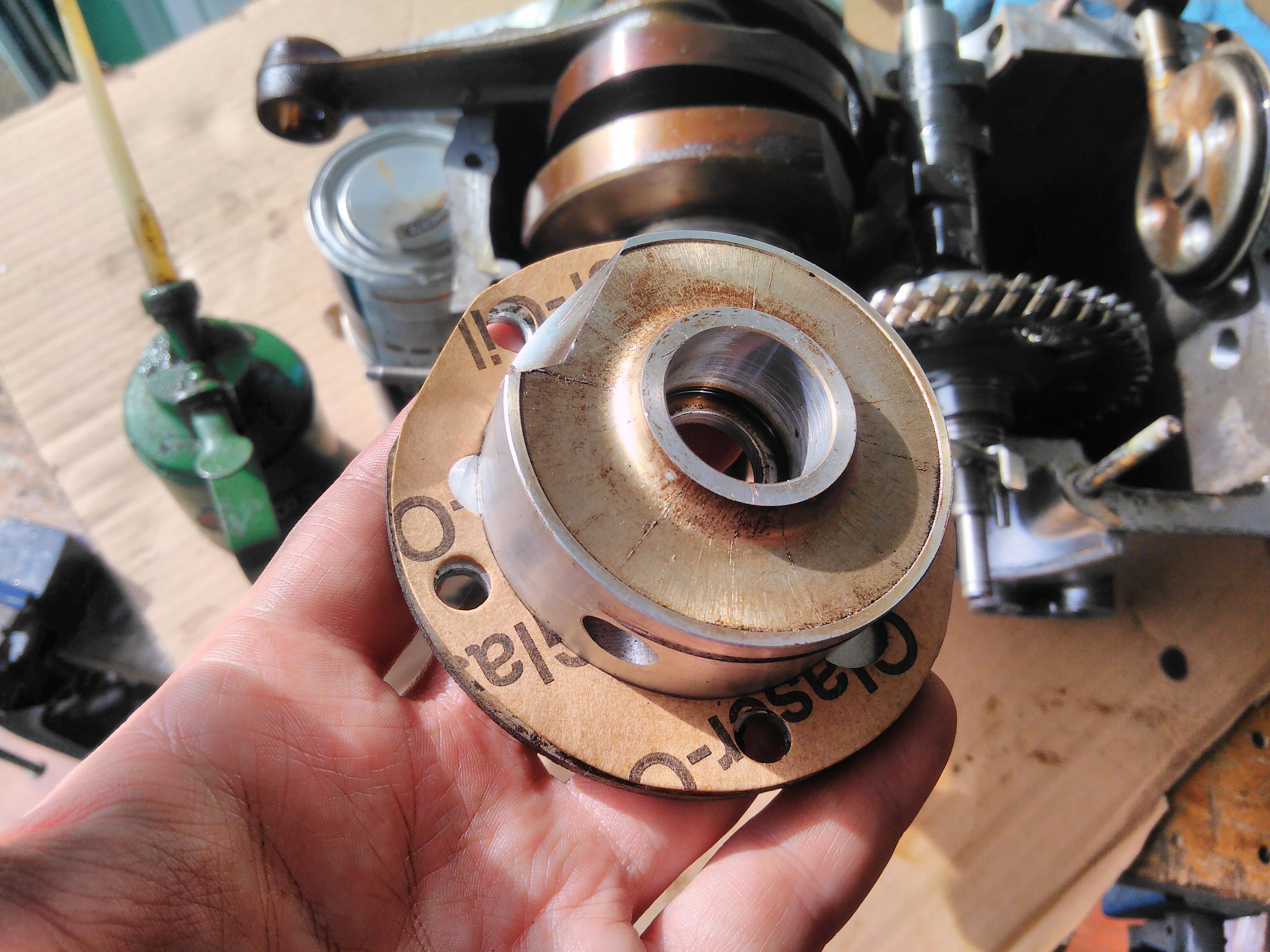
The housing fits into the crank case first. There is a flat that goes at the top, next to the crank shaft – this ensures the oil galleries line up correctly.
The the inner rotor goes on next, it has a flat that goes onto the flat at the end of the cam shaft.

The outer rotor goes on last as it can be easily rotated to the point where it fits with the inner rotor.

The oil pump cover receives a new o-ring and some sealant round the outer edge before it is bolted on. In order to align these bolts with the oil pump and the crank case the pump housing may need to be rotated which is why the crank case bolts haven’t been tightened yet.
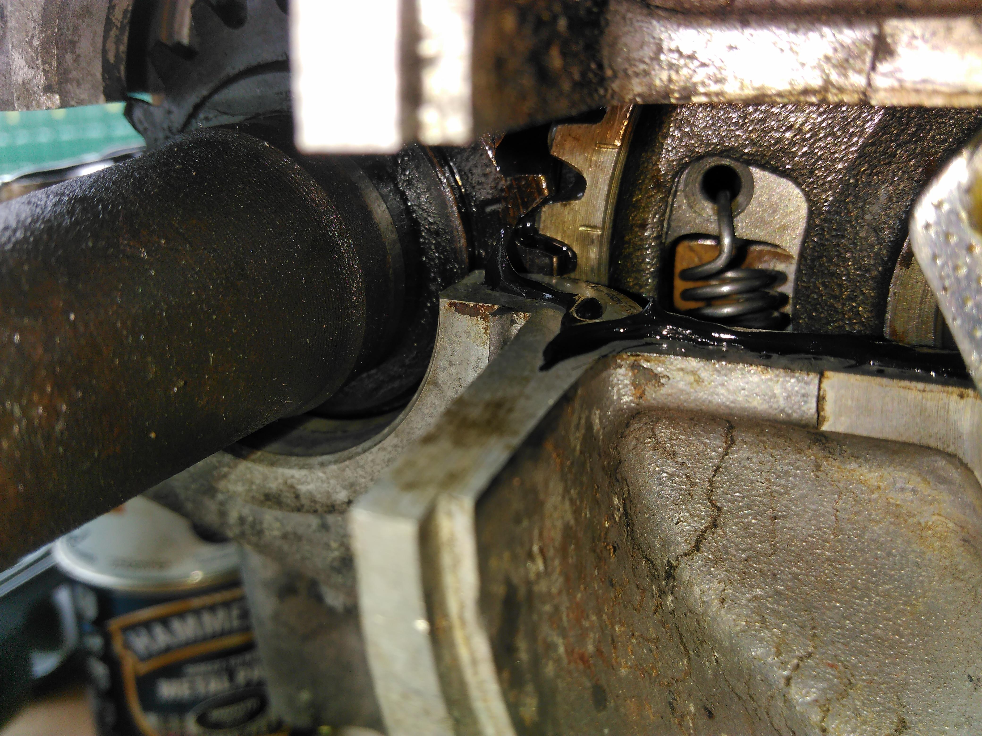
With the oil pump in place, the crank case bolts can now be tightened according to the sequence and torque settings in the manual.

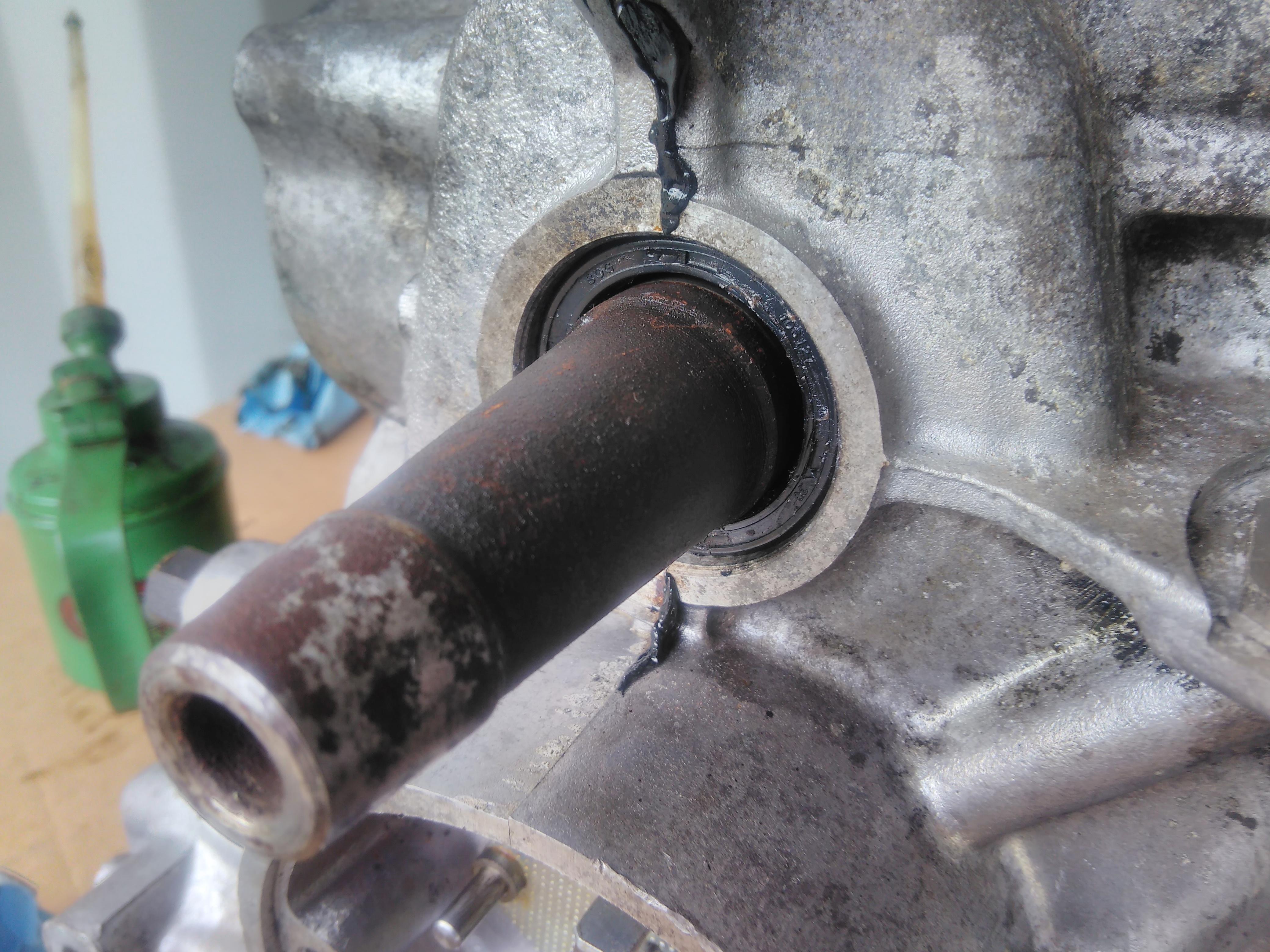
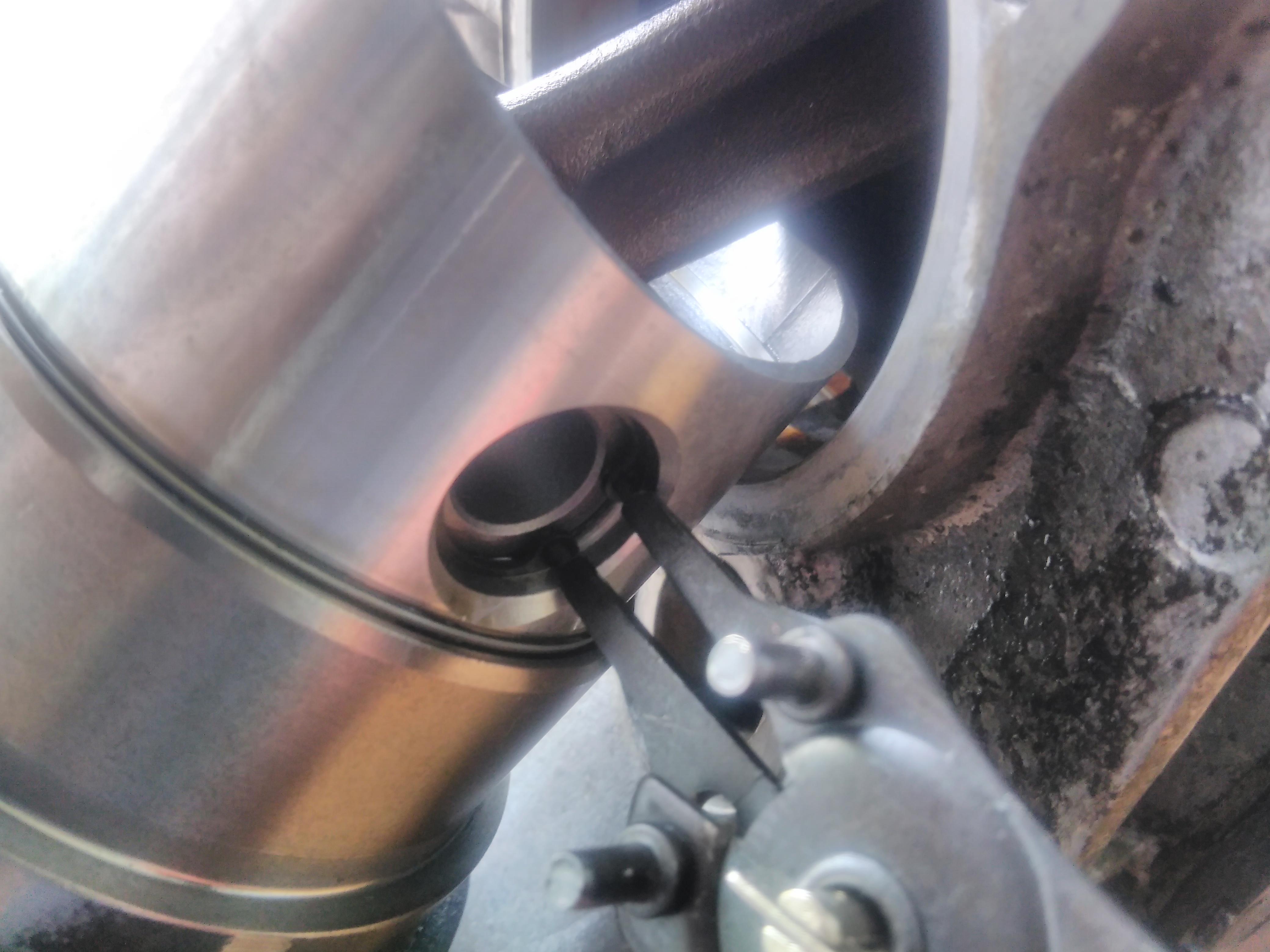
The two crank shaft oil seals can now be fitted. The are a push fit but the tolerances are tight so use plenty of lubrication (also prevents them tearing when first running) and carefully drift them into place.

Now’s a good time to put the tappets in – I’m using new tappets as I have a new cam shaft. These are a tight fit and plenty of lubrication is necessary.

The cylinders had previously been lapped to the crank case so time to fit the pistons. With some light persuasion the gudgeon pins slide through the pistons and the con-rod little end bearings.
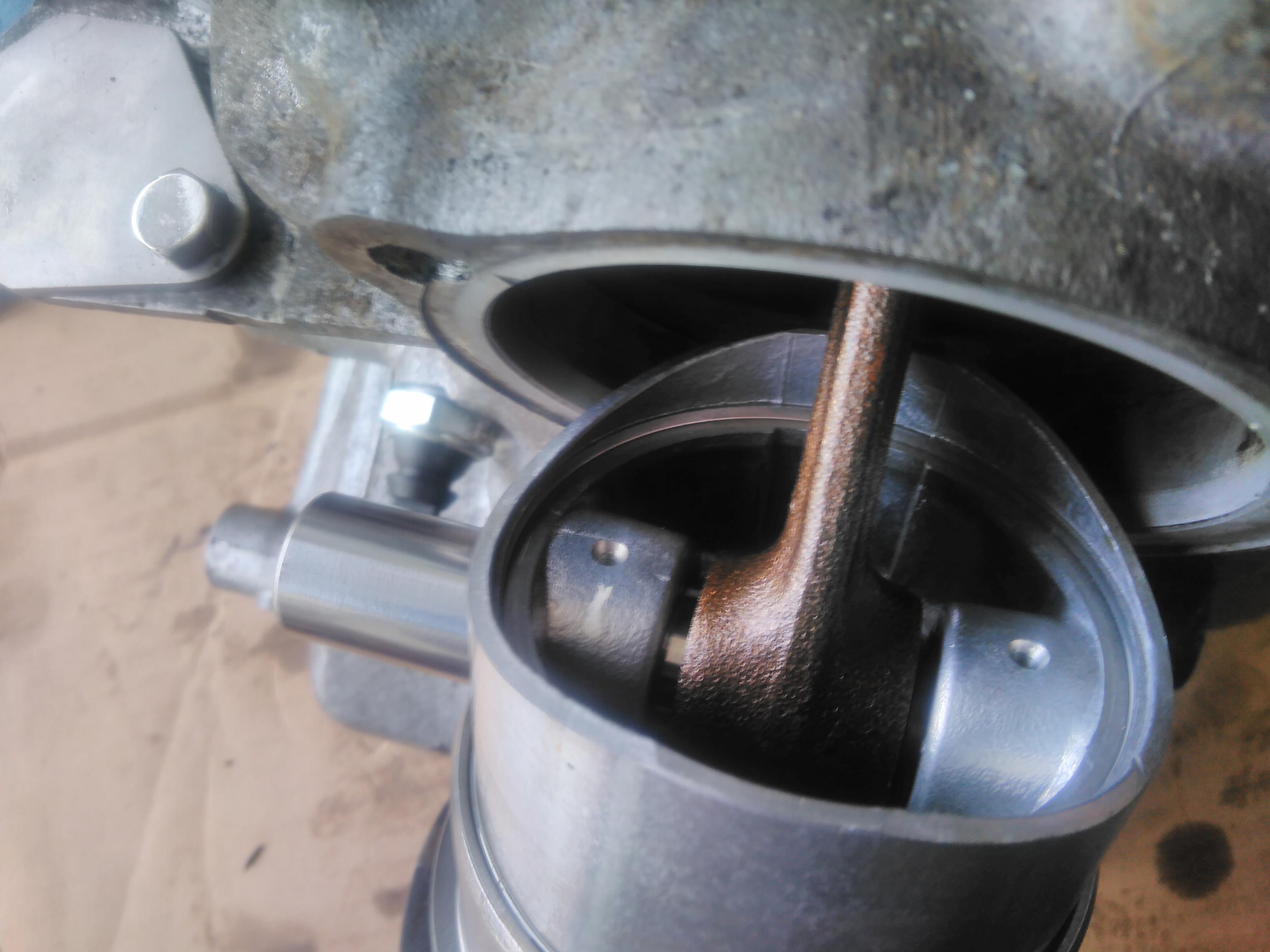
With the gudgeon pin mostly through the retaining circlip can be fitted. The gudgeon pin can then be pushed through until it seats on the clirclip at which point the other circlip can be fitted.
Next step will be to fit the heads.


As the wiring loom I’m working with was from a car that came with the dim-dip system I removed it entirely – including all the extra wires added to the loom.
Most of these wires were added to the loom at crimp connectors so cutting them out cleanly was easy.
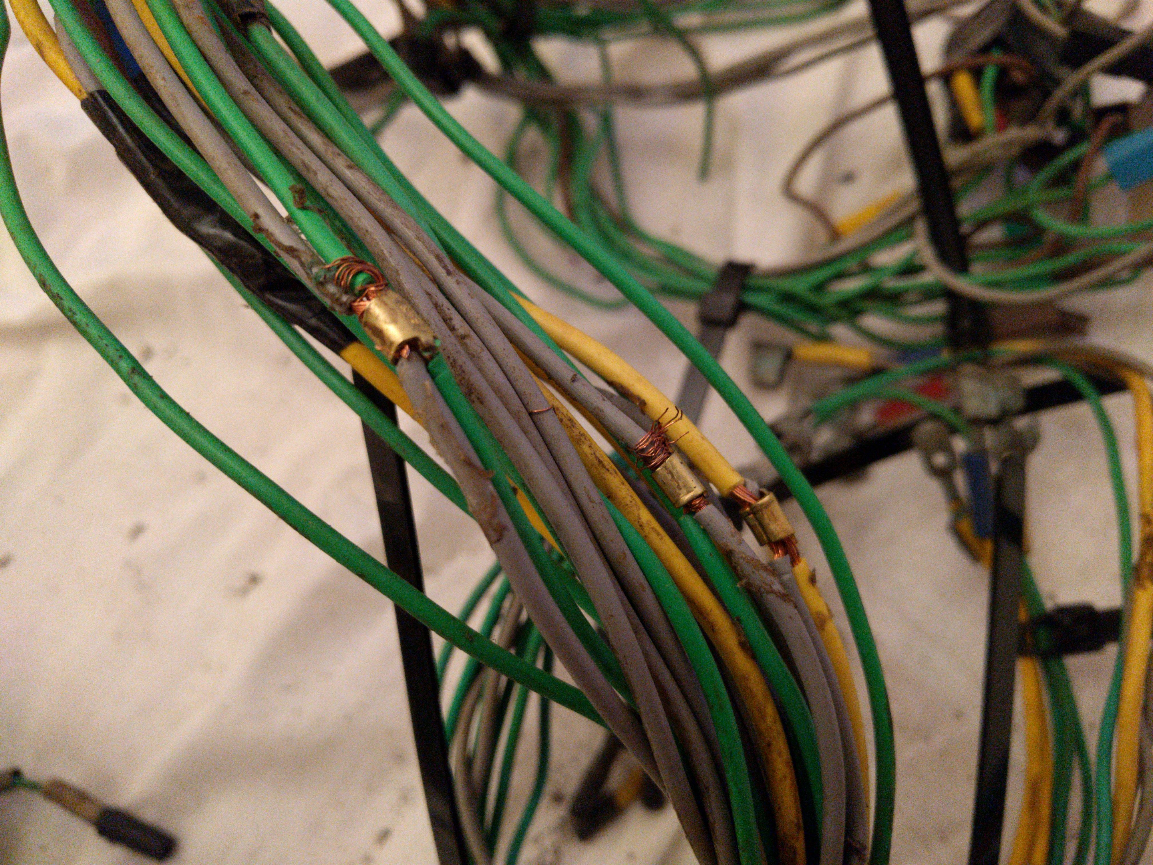
The relay one bypass was also easy to do neatly with an insulated crimp connector.


As I’ve had nothing but trouble with the wiring of the wings I’m re-wring both of them so I know where I am.
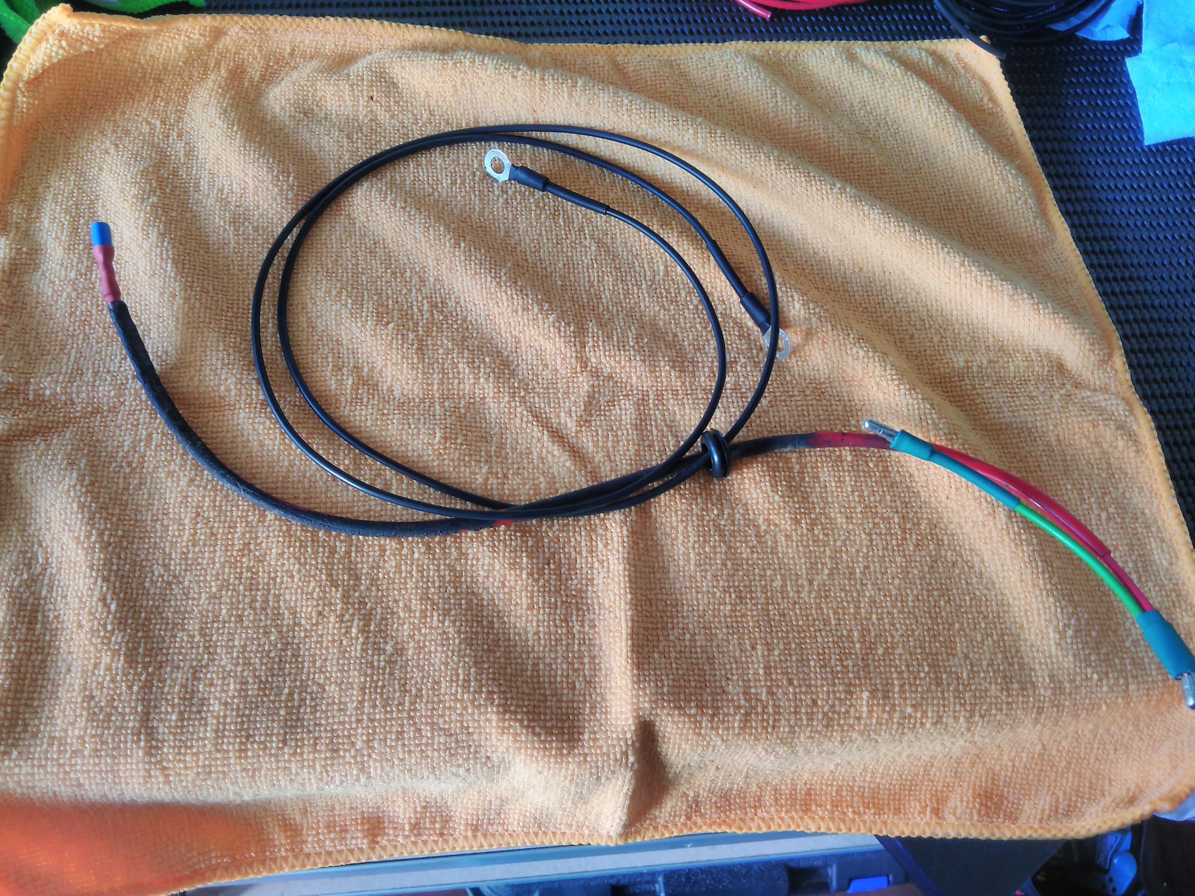
First step is to work out the wiring diagram, it’s not complicated but having something like this to work from makes the job easier.
(Note that I’ve added a blade connector onto the back of the indicator, normally that wire runs directly from the indicator’s bulb live connector to the main wiring loom’s bullet connector. Adding the blade connector makes it easier to remove/ replace the indicator as you don’t have to cut that wire.)
The indicator live (red) and earth (black) both run through a 12mm grommet at the front. The live runs through a red sleeve.

The indicator earth attaches to the indicator via the upper retaining bolt. It’s important it’s the top bolt as the head is connected to the earth of the bulb inside the assembly.
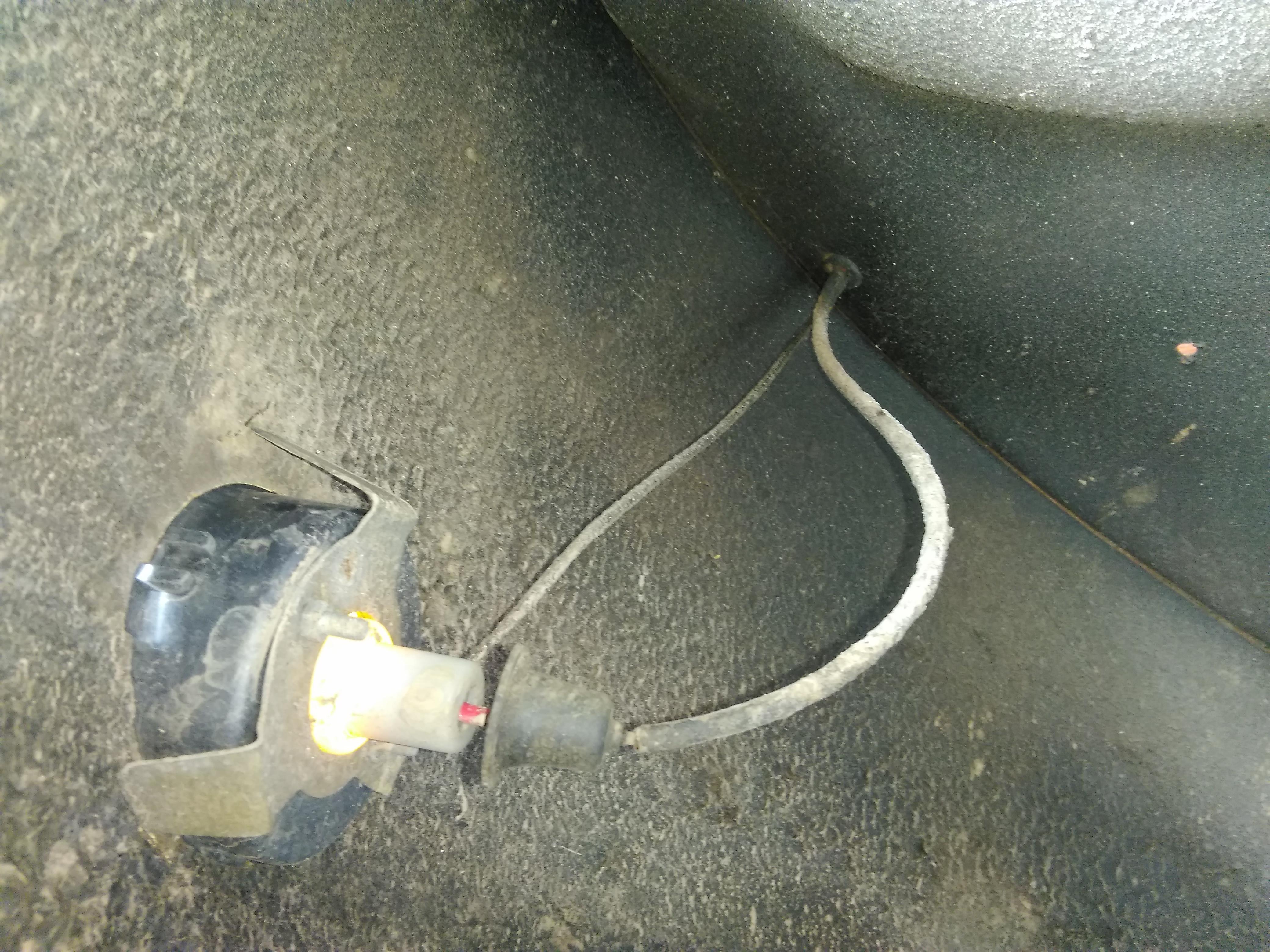
The repeater live runs through a grey sleeve and connects to the repeater via a blade connector.
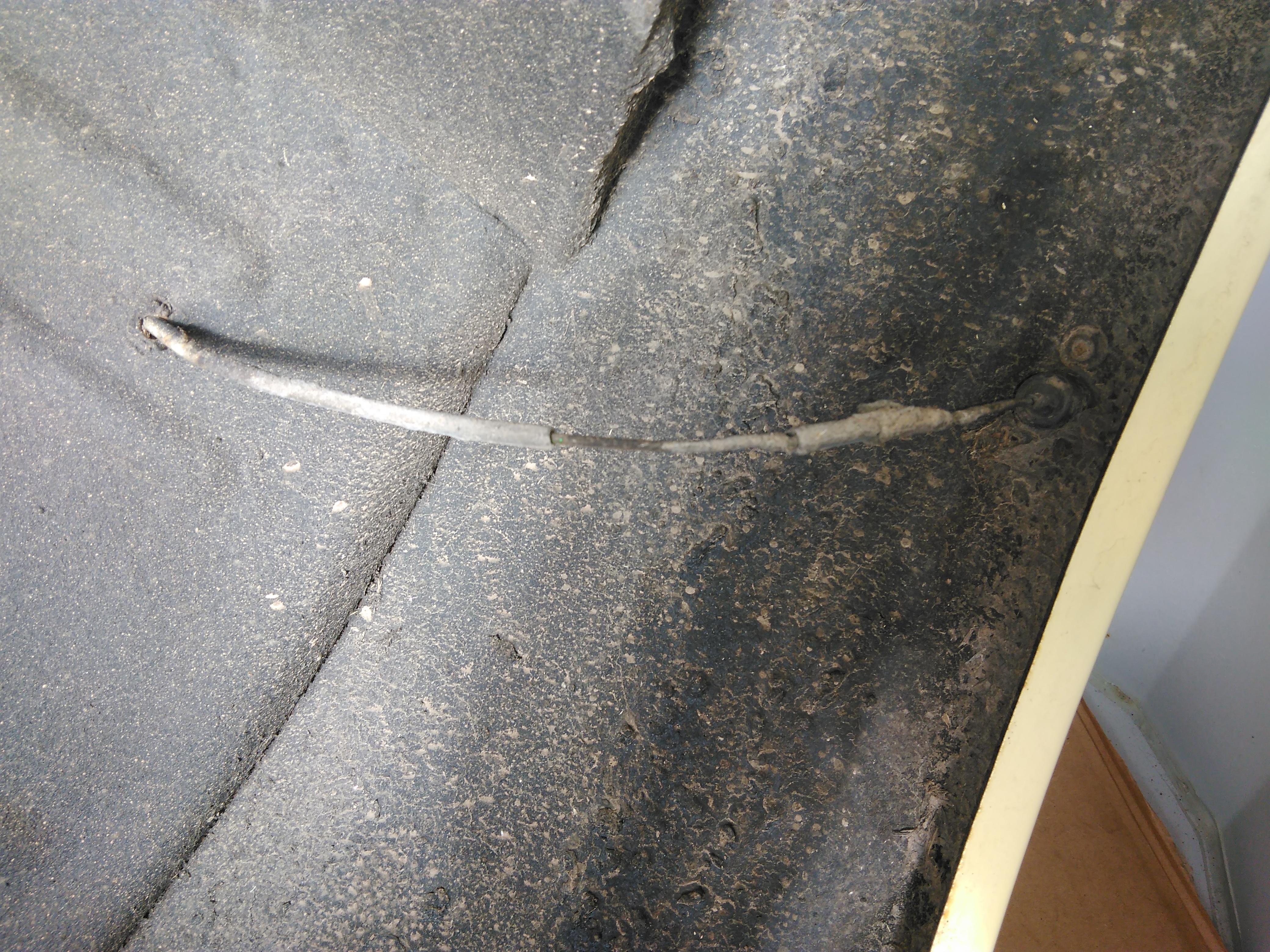
With the wires cut to length the connectors go on and I’ve added heat shrink over them to tidy them up, keep the clart out and take a bit of stress off the wire where it enters the crimped connectors.
Reading Mal’s writing on shooting reminded me of the enjoyment I used to get from shooting targets in the back garden with an air rifle. However, in the intervening 25 years the laws surrounding air rifle ownership have changed significantly meaning that’s not an option for me these days. Fortunately the rise of global capitalism and advances in manufacturing technologies means that I can select from a wide range of Nerf guns at the local toy superstore.
A while back I picked up the “Centurion”, it’s basically Nerf’s take on an anti-material rifle.

Whilst the ergonomics are pretty darn good for prone shooting the ballistics of the “Mega” darts are fracking terrible. On a six meter range from my kitchen, across the hall, to the spare room I couldn’t reliably hit a duster hung over the laundry bin!

Another friend of mine had said the Rival Apollo was worth a look, it has a much stronger main spring and the Rival ammo (essentially small yellow foam golf balls) has a good ballistic trajectory.
The Apollo is Nerf’s take on a bolt action bullpup sub machine gun(‽) and the prone shooting ergonomics are pretty much what you’d expect from that configuration – fracking terrible.
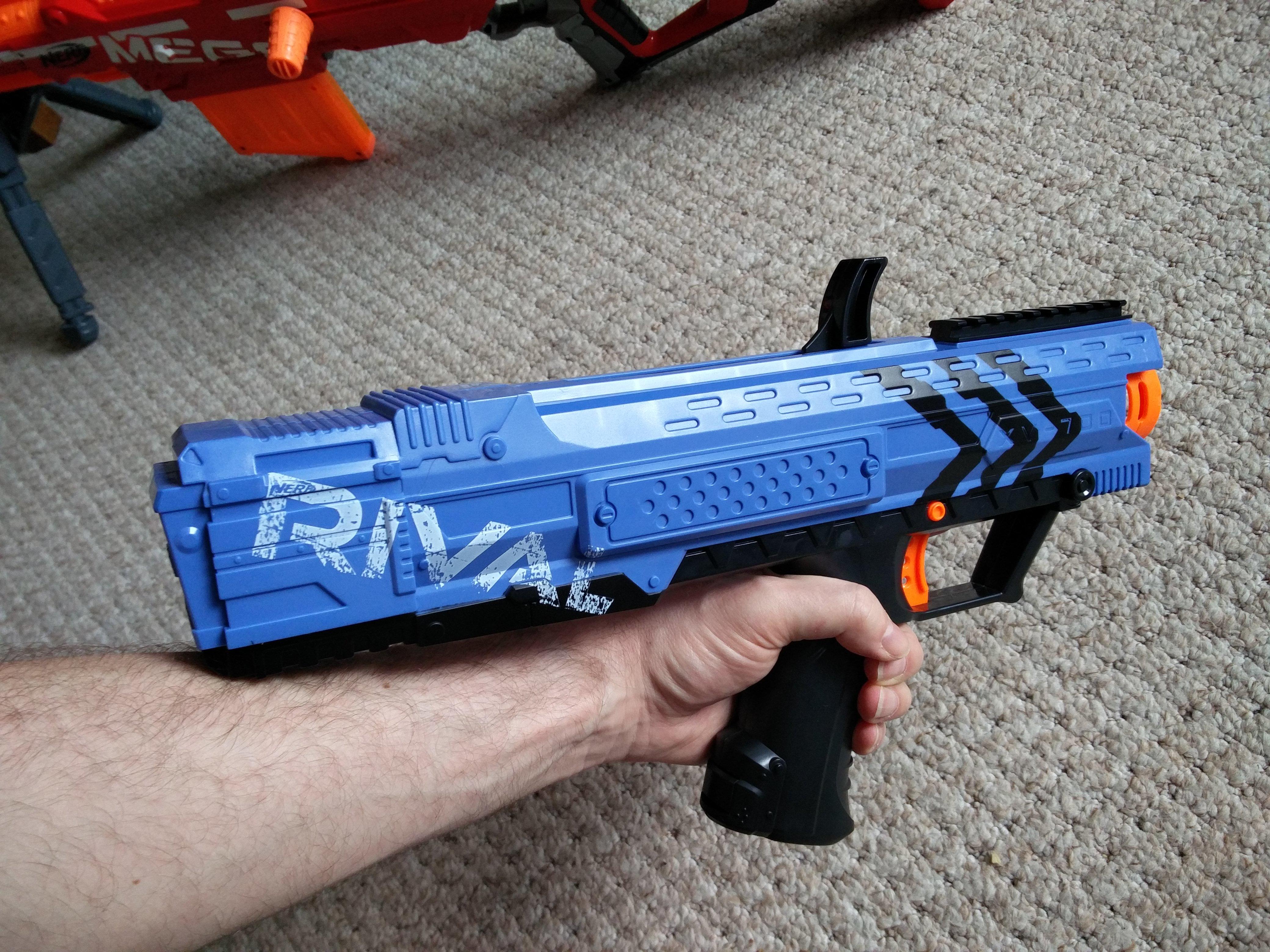
The magazine (not present in the photos) is located in the pistol grip and sticks out the bottom, the charging handle is on the top and there’s no butt plate.

It is possible to shoulder it but it’s short and the hard square edges on the rear of the receiver are not comfortable.
So I now have one gun with great ergonomics and terrible ballistics and one with great ballistics and terrible ergonomics – I’m sure you can see where this is going…

My plan is to take the action from the Apollo and and put it into the furniture of the Centurion. At first inspection the receiver of the Apollo and the butt of the Centurion seem about the same size so the next step will be to take things apart and see what’s what.