


Picked up the Twin Spin Helicopter set as it has some parts that look like they will be useful for the Gee Bee.
One of the models is a propeller plane that looks like a good base for a smaller Gee Bee.

Nothing to see here.
Picked up the Twin Spin Helicopter set as it has some parts that look like they will be useful for the Gee Bee.
One of the models is a propeller plane that looks like a good base for a smaller Gee Bee.

Having built the 24 Hours Race Car and not been overly impressed with the functionality I decided to remedy that situation by making it remote control.
Out of the box the car is set up for motorisation with a compartment in the nose for the battery box but the preprepared motor location is intended to drive the door and engine cover.
In addition to the battery box and motors the “Power Functions” range contains a two channel remote control and a servo which provides everything needed.
After stripping out most of the sets of axles that weaved across the bottom of the car to make the doors and engine cover lift from a single dive there was enough space to start working.
It took a few attempts but I managed to get the motor drive shaft to connect into the V8 engine crank shaft which then goes through the diff into the rear wheels. The downside of this is that the pinion is under a lot of torque as it meshes with the ring gear and can slip off the input shaft.

With the “hand of god” steering wheel and linkages removed the steering servo fitted into the cockpit and interfaced cleanly with the pinion shaft.

The IR receiver for the remote control fits in where the steering wheel was previously located which gives good reception.


Since I’d removed all the cross linked axles to make space for the motors the doors and engine cover no longer operated. However, as the actuators were still there, I re-worked the drive shafts so rather than going from a drive at the rear of the right side pod to a clutch at the front of the left side pod and back to the actuators on either side at the rear they now have individual drives at the rear of each side pod via the shortest route possible into the actuators.

The end result is that I not only have remote control drive and steering but I’ve retained and improved the existing functionality for the doors and engine cover. Oh, and the headlights light up.
Credit for the original solution of the dim-dip removal goes to John Wood:
Back in Feb 1995 I wrote to the editor (then Bev Abbot) regarding light switches getting hot, which had been of concern to many drivers of late model cars at that time. I had noticed my own switch getting quite warm, particularly at the connector where a Mauve wire was attached and decided to find out why this was happening and if I could do anything to cure this problem. I had just got a new edition of Haynes which had details of the Dim – Dip system which Citroen had cobbled together in order to comply with new regs in UK and maybe in other countries. After studying the new circuit I found that the Mauve wire was carrying all of the current to the lights unlike in earlier models, without Dim – Dip, where the load was shared between two switch terminals and two wires. I decided to ditch Dim – Dip and return the circuit to standard and set about studying the circuit. After a bit more puzzling I discovered that it was possible to achieve my aim by the deceptively simple method of disconnecting the relays and using a ‘jumper lead’ to bridge connectors 1 and 5 of the plug which has 5 wires going to it. The Dim – Dip Resistor which is mounted on the front cross member of the chassis can also be removed as can the Diode which can be found tied to the Flasher unit under the parcel shelf although this is not essential as they are no longer in the circuit once the relays are removed. The relays are installed to make the Dim – Dip system work. However, the system is flawed in it’s design, causing the overheating at the switch terminal. Removing the relays enables my method of using a jumper lead to return the circuit to standard to be employed.

My favourite Technic Lego set from my youth was the Big Car so its contemporary equivalent – especially being an LMP1 racer – had always appealed to me.
It’s a sizeable kit with a lot of parts and a 250 page instruction book.

This is the first time I’ve really encountered the studless style of Technic and I have to say it’s more like Meccano than Lego as far as I’m concerned.
It took most of an afternoon and evening to assemble it following the instructions.

Whilst it looks very good – there’s no question it’s modelled on an LMP1 endurance racer – I wasn’t particularly impressed with the functionality. About the only thing that wasn’t present on the model I had 30 years ago is the front suspension.
There is a steering wheel but it’s not connected to anything, the steering is controlled by a cog on the top of the car – something I’ve never been too keen on.
The engine cover lifts and the gull-wing doors work from a single cog on the right side, switched by a clutch in the left side pod. This is a nicely executed feature but there are an awful lot of cogs and axles around the cockpit and side pods.

Hopefully the final stage in the saga of the battery tray is the addition of a reinforcement plate.

This has a box section that sits on the rib that runs across the bulkhead which transfers the load of the battery vertically down.

Without this the centre of gravity sits out ahead of the bulkhead and creates a rotational force which creates stress leading to cracks.
With the reinforcement plate painted to match the bulkhead it does a good job of covering up the riveted patch plates and will hopefully mean this area of the car doesn’t need more attention.

I’ve got a pair of aluminium Robri trims that were a present from my parents as they were a feature of some of the 2CVs I grew up with.
They come with 4mm mounting holes with moulded countersink and I’ve picked up some stainless steel bolts with countersunk alan heads and nylock nuts.
The moulded countersinks are fairly rough and the bolts heads stand proud as they don’t fully drop into the trims.

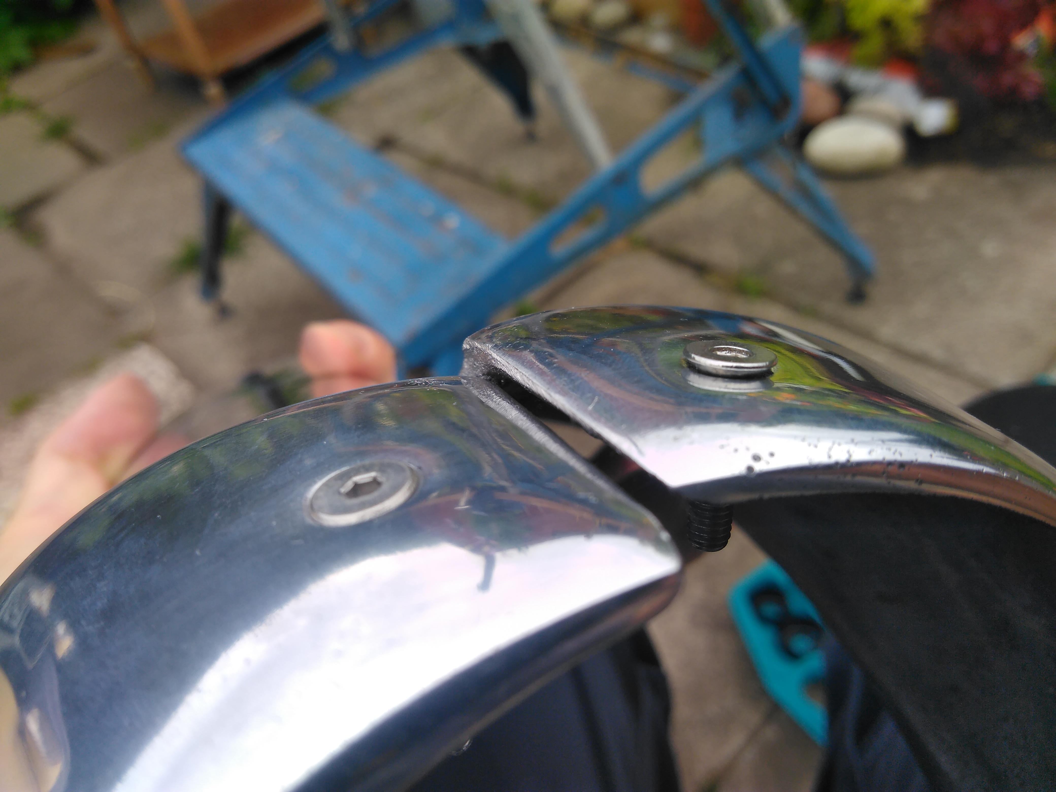
Using a countersink bit I drilled out the holes so the bolts will sit flush. As the cast aluminium is relatively soft it’s easy to remove more material than required so I took my time and kept checking with a bolt to ensure I finished when it was flush with the surface of the trim.

The 2CV’s two cylinder boxer engine configuration means the crank case volume changes with each revolution of the crank, reducing as the two pistons come towards each other on the inlet/power stroke and away from each other on the exhaust/compression stroke.
If the crank case was a sealed system this change in volume would cause resistance to the running of the engine. To prevent this the crank case has a breather that vents through the oil filler and out to the air box.
The breather is fitted with one-way valves that allow the air out of the crank case but not back in thus maintaining a negative pressure. This negative pressure has the advantage that the oil has a tendency to be drawn back into the engine rather than leak out.

To ensure these one-way valves are functioning the crank case vacuum should be tested with a manometer – the pressure differential here is quite low (~0.1 psi) so a normal vacuum gauge typically won’t be sensitive enough to show a reading. Per the Citroën workshop manual, this vacuum should not drop below 5cm even at high revs. (At high revs there is less time for the air to be pushed out of the crank case as the pistons move towards each other before they move out again.)
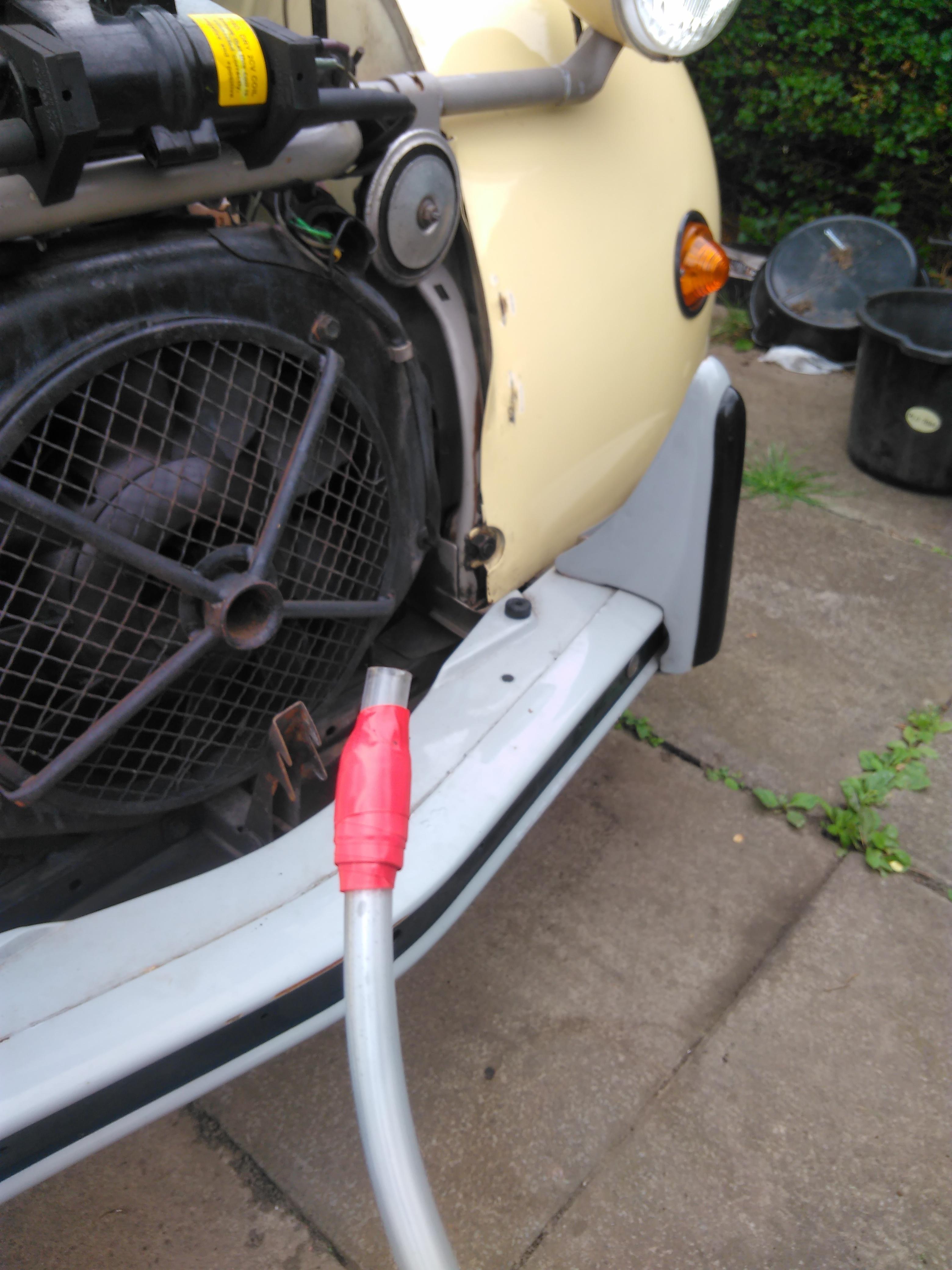
There are various options for a manometer – from the simplest being a loop of tubing up to one made to the same specifications as the original Citroën workshop tool (MR. 630-56/9a) that is available from Burton. I went with a generic plumber’s manometer from an on-line retailer.
I also added a liquid trap to the engine side of the manometer to prevent water being sucked into the crank case but another option is to use LHM fluid as this won’t contaminate the oil if it does get into the engine.

(The water level doesn’t show up too well in these photos so I’ve highlighted it, a bit of dye would mean the level is more obvious but, when you’re actually stood in front of it, seeing the water level isn’t a problem.)
With one end of the manometer open to the atmosphere the other is connected to the inside of the crank case via the dipstick opening. The 6mm (inside diameter) PVC tubing I’m using wasn’t large enough to seal so some insulating tape wrapped round the end did the job.
Make sure the engine is nicely warmed up then take out the dipstick and connect the manometer to the crank case via the dipstick tube.

With the engine idling, gently rev it a couple of times to stabilise the fluid level in the manometer. We’re now ready to take a reading.
At idle, the water level on the engine side should be at least 5cm higher than the side open to the atmosphere – indicating the pressure in the crank case is lower.
Keeping an eye on the water levels, rev the engine all the way up to full throttle – we’re expecting the water level to fall but it should never get low enough to be level with the side open to the atmosphere.
A vacuum of less than 5cm at idle or dropping to zero at high revs indicates that the one-way valve in the breather has failed and needs to be replaced.
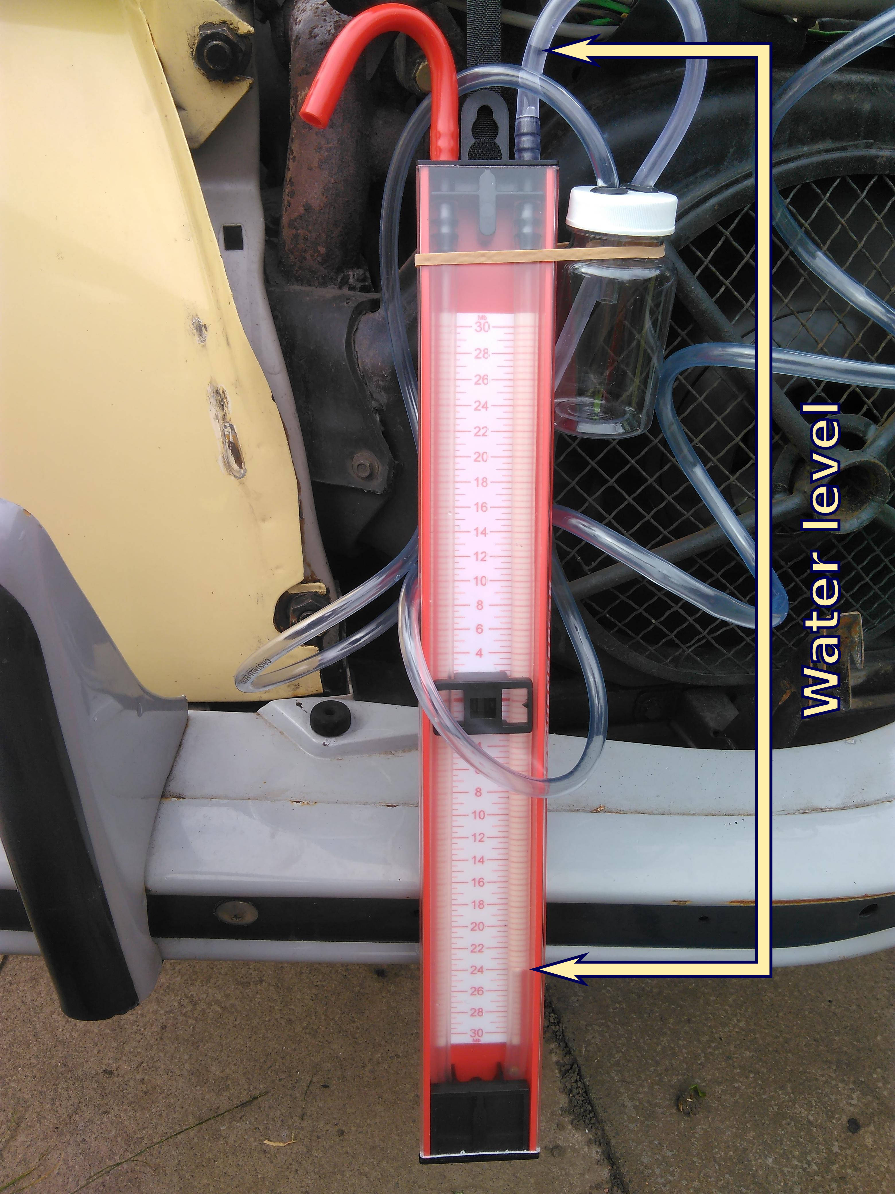
I was pleasantly surprised to see that Judith was showing a vacuum of over 30cm , especially as the breather hasn’t been replaced recently – if ever.

Playing around with an infra-red camera and took a couple of pictures of Judith’s engine when it was running. The effect of the cooling ducts moving the heat away from the cylinder headers is clear.
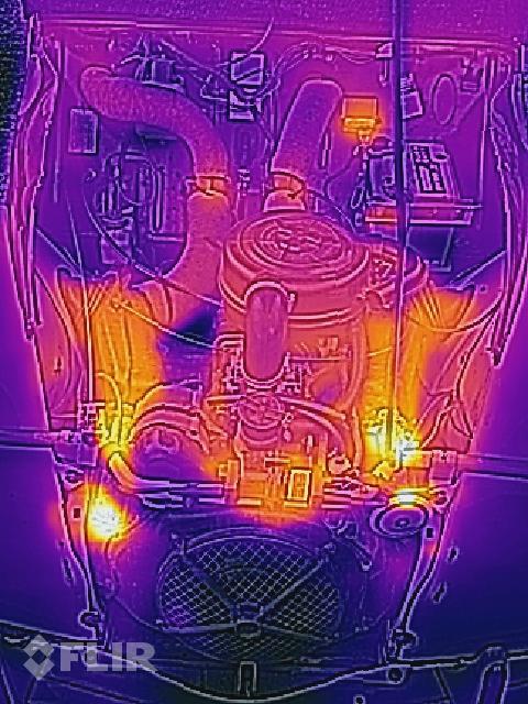
From underneath the sump, which is part of the engine block, is the main heat source.


Spent some time today re-working the fuselage of the stock Aviation Adventures kit to make it look more like a Gee Bee Model R.
At this point I’m working entirely with the parts that came with the kit, I’ve not delved into my bits box, so whilst some of the colours aren’t ideal I’m happy with the overall shape I’ve achieved.


It’s now recognisable as having the characteristic shape of a Gee Bee racer but the wings are much too big – tackling them will be the next task on this build.